Product Description
Specification OF PTO Drive Shaft —Speedway:
We developed and produced many tractor spare parts for Japanese Tractors .
Product Name: Japanese tractor transmission clutch disc parts for B1400 B7000
Tractor Model we can supply: B1500/1400,B5000,B6000, B7000, TU1400, TX1400, TX1500, YM F1401, YM1400 ETC.
The parts for example: Tyres, rim Jante, Kit coupling KB-TX 3 point linkage. Exhaust pipe Steering wheel. Kit coupling YM F14/F15, gear shaft, PTO shaft, PTO cardan, key, regulator ect.
Most of the spare parts are with stock. If you are interested in, please feel easy to contact me.
Other relevant parts for cars or machinery we have made in our workshop are as follows:
Drive shaft parts and assemblies,
Universal joint parts and assemblies,
PTO drive shafts,
Spline shafts,
Slip yokes,
Weld yokes,
Flange yokes,
Steering columns,
Connecting rods,
etc.
Product Description
Pto Drive Shaft Item:
| Item | Cross journal size | 540dak-rpm | 1000dak-rpm | |||
| Series 1 | 22mm | 54mm | 12KW | 16HP | 18KW | 25HP |
| Series 2 | 23.8mm | 61.3mm | 15KW | 21HP | 23KW | 31HP |
| Series 3 | 27mm | 70mm | 26KW | 35HP | 40KW | 55HP |
| Series 4 | 27mm | 74.6mm | 26KW | 35HP | 40KW | 55HP |
| Series 5 | 30.2mm | 80mm | 35KW | 47HP | 54KW | 74HP |
| Series 6 | 30.2mm | 92mm | 47KW | 64HP | 74KW | 100HP |
| Series 7 | 30.2mm | 106.5mm | 55KW | 75HP | 87KW | 18HP |
| Series 8 | 35mm | 106.5mm
|
70KW | 95HP | 110KW | 150HP |
| Series 38 | 38mm | 102mm | 70KW | 95HP | 110KW | 150HP |
Company Profile
Certifications
FAQ
/* January 22, 2571 19:08:37 */!function(){function s(e,r){var a,o={};try{e&&e.split(“,”).forEach(function(e,t){e&&(a=e.match(/(.*?):(.*)$/))&&1
| Type: | Shaft |
|---|---|
| Usage: | Agricultural Products Processing, Farmland Infrastructure, Harvester, Planting and Fertilization, Grain Threshing, Cleaning and Drying |
| Material: | Stainless Steel |
| Power Source: | Pto Dirven Shaft |
| Weight: | Standard |
| After-sales Service: | 1 Year |
| Samples: |
US$ 300/Piece
1 Piece(Min.Order) | |
|---|
What maintenance practices are essential for prolonging the lifespan of cardan shafts?
Maintaining proper maintenance practices is crucial for prolonging the lifespan of cardan shafts and ensuring their optimal performance. Here are some essential maintenance practices to consider:
1. Regular Lubrication:
– Proper lubrication of the cardan shaft’s universal joints is vital for reducing friction, preventing wear, and ensuring smooth operation. Regularly lubricate the universal joints according to the manufacturer’s recommendations using the appropriate lubricant. This helps to minimize frictional losses, extend the life of the needle bearings, and maintain the efficiency of power transfer.
2. Inspection and Cleaning:
– Regular inspection and cleaning of the cardan shaft are essential for identifying any signs of wear, damage, or misalignment. Inspect the shaft for any cracks, corrosion, or excessive play in the universal joints. Clean the shaft periodically to remove dirt, debris, and contaminants that could potentially cause damage or hinder proper operation.
3. Misalignment Adjustment:
– Check for any misalignment between the driving and driven components connected by the cardan shaft. If misalignment is detected, address it promptly by adjusting the alignment or replacing any worn or damaged components. Misalignment can lead to increased stress on the shaft and its components, resulting in premature wear and reduced lifespan.
4. Balancing:
– Periodically check the balance of the cardan shaft to ensure smooth operation and minimize vibration. If any imbalance is detected, consult with a qualified technician to rebalance the shaft or replace any components that may be causing the imbalance. Balanced cardan shafts promote efficient power transfer and reduce stress on the drivetrain.
5. Torque and RPM Monitoring:
– Keep track of the torque and RPM (revolutions per minute) values during operation. Ensure that the cardan shaft is not subjected to torque levels exceeding its design capacity, as this can lead to premature failure. Similarly, avoid operating the shaft at speeds beyond its recommended RPM range. Monitoring torque and RPM helps prevent excessive stress and ensures the longevity of the shaft.
6. Periodic Replacement:
– Despite regular maintenance, cardan shafts may eventually reach the end of their service life due to normal wear and tear. Periodically assess the condition of the shaft and its components, considering factors such as mileage, operating conditions, and manufacturer recommendations. If significant wear or damage is observed, it may be necessary to replace the cardan shaft to maintain optimal performance and safety.
7. Manufacturer Guidelines:
– Always refer to the manufacturer’s guidelines and recommendations for maintenance practices specific to your cardan shaft model. Manufacturers often provide detailed instructions regarding lubrication intervals, inspection procedures, and other maintenance requirements. Adhering to these guidelines ensures that the maintenance practices align with the manufacturer’s specifications, promoting the longevity of the cardan shaft.
By following these essential maintenance practices, you can prolong the lifespan of cardan shafts, optimize their performance, and minimize the likelihood of unexpected failures. Regular maintenance not only extends the life of the cardan shaft but also contributes to the overall efficiency and reliability of the systems in which they are utilized.

How do cardan shafts handle variations in load, speed, and misalignment during operation?
Cardan shafts are designed to handle variations in load, speed, and misalignment during operation. They incorporate specific features and mechanisms to accommodate these factors and ensure efficient power transmission. Let’s explore how cardan shafts handle these variations:
1. Load Variation:
– Cardan shafts are designed to transmit torque and handle variations in load. The torque capacity of the shaft is determined based on the application’s requirements, and the shaft is manufactured using materials and dimensions that can withstand the specified loads. The design and construction of the shaft, including the selection of universal joints and slip yokes, are optimized to handle the anticipated loads. By choosing appropriate material strengths and dimensions, cardan shafts can effectively transmit varying loads without failure or excessive deflection.
2. Speed Variation:
– Cardan shafts can accommodate variations in rotational speed between the driving and driven components. The universal joints, which connect the shaft’s segments, allow for angular movement, thereby compensating for speed differences. The design of the universal joints and the use of needle bearings or roller bearings enable smooth rotation and efficient power transmission even at varying speeds. However, it’s important to note that excessively high speeds can introduce additional challenges such as increased vibration and wear, which may require additional measures such as balancing and lubrication.
3. Misalignment Compensation:
– Cardan shafts are specifically designed to handle misalignment between the driving and driven components. They can accommodate angular misalignment, parallel offset, and axial displacement to a certain extent. The universal joints in the shaft assembly allow for flexibility and articulation, enabling the shaft to transmit torque even when the components are not perfectly aligned. The design of the universal joints, along with their bearing arrangements and seals, allows for smooth rotation and compensation of misalignment. Manufacturers specify the maximum allowable misalignment angles and displacements for cardan shafts, and exceeding these limits can lead to increased wear, vibration, and reduced efficiency.
4. Telescopic Design:
– Cardan shafts often feature a telescopic design, which allows for axial movement and adjustment to accommodate variations in distance between the driving and driven components. This telescopic design enables the shaft to handle changes in length during operation, such as when the vehicle or equipment undergoes suspension movement or when the drivetrain components experience positional changes. The telescopic mechanism ensures that the shaft remains properly connected and engaged, maintaining power transmission efficiency even when there are fluctuations in distance or position.
5. Regular Maintenance:
– To ensure optimal performance and longevity, cardan shafts require regular maintenance. This includes inspections, lubrication of universal joints and slip yokes, and monitoring for wear or damage. Regular maintenance helps identify and address any issues related to load, speed, or misalignment variations, ensuring that the shaft continues to function effectively under changing operating conditions.
Overall, cardan shafts handle variations in load, speed, and misalignment through their design features such as universal joints, telescopic design, and flexibility. By incorporating these elements, along with proper material selection, lubrication, and maintenance practices, cardan shafts can reliably transmit torque and accommodate the changing operating conditions in vehicles and equipment.
How do cardan shafts handle variations in angles, torque, and alignment?
Cardan shafts, also known as propeller shafts or drive shafts, are designed to handle variations in angles, torque, and alignment between the driving and driven components. They possess unique structural and mechanical features that enable them to accommodate these variations effectively. Let’s explore how cardan shafts handle each of these factors:
Variations in Angles:
– Cardan shafts are specifically designed to handle angular misalignment between the driving and driven components. This misalignment can occur due to factors such as changes in suspension height, flexing of the chassis, or uneven terrain. The universal joints used in cardan shafts allow for angular movement by employing a cross-shaped yoke with needle bearings at each end. These needle bearings facilitate the rotation and flexibility required to compensate for angular misalignment. As a result, the cardan shaft can maintain a consistent power transmission despite variations in angles, ensuring smooth and efficient operation.
Variations in Torque:
– Cardan shafts are engineered to withstand and transmit varying levels of torque. Torque variations may arise from changes in load, speed, or resistance encountered during operation. The robust construction of the shaft tubes, coupled with the use of universal joints and slip yokes, allows the cardan shaft to handle these torque fluctuations. The shaft tubes are typically made of durable and high-strength materials, such as steel or aluminum alloy, which can withstand high torsional forces without deformation or failure. Universal joints and slip yokes provide flexibility and allow the shaft to adjust its length, absorbing torque fluctuations and ensuring reliable power transmission.
Variations in Alignment:
– Cardan shafts are adept at compensating for misalignment between the driving and driven components that can occur due to manufacturing tolerances, assembly errors, or structural changes over time. The universal joints present in cardan shafts play a crucial role in accommodating misalignment. The needle bearings within the universal joints allow for slight axial movement, permitting misaligned components to remain connected without hindering torque transmission. Additionally, slip yokes, which are often incorporated into cardan shaft systems, provide axial adjustability, allowing the shaft to adapt to changes in the distance between the driving and driven components. This flexibility in alignment compensation ensures that the cardan shaft can effectively transmit power even when the components are not perfectly aligned.
Overall, cardan shafts handle variations in angles, torque, and alignment through the combination of universal joints, slip yokes, and robust shaft tube construction. These features allow the shaft to accommodate angular misalignment, absorb torque fluctuations, and compensate for changes in alignment. By providing flexibility and reliable power transmission, cardan shafts contribute to the smooth operation and longevity of various systems, including automotive drivetrains, industrial machinery, and marine propulsion systems.


editor by CX 2024-05-17
China supplier Turning Milling Precison Part CNC Machining Stepped Stainless Drive Shaft for Medical Drive Line
Product Description
Company Profile
—–ABOUT US—–
Focuses on the research, development, production, sales and service of fasteners, precision hardware parts and various metal products.
HangZhou CZPT CZPT Technology Co., Ltd. was established on March 1, 2016. It is located in Xihu (West Lake) Dis.ang District, HangZhou City, ZheJiang Province. It covers an area of 5600 square CZPT and focuses on the research, development, production, sales and service of fasteners, precision hardware parts and various metal products. The processed products are mainly cold heading, forging, precision turning, milling, assembly, stamping, supplemented by extrusion, upsetting and casting. In addition, we also have rich experience in anodizing, electroplating and heat treatment.
Product Parameters
| No. | Item | Specifications |
| 1 | Materials | Carbon steel: 12L15, 45#, 42CrMo; Stainless steel: 303, 304, 316, 420, 630; Aluminum alloy: 6061, 6063, 5052, 7075; Copper alloy: brass H58-H63, phosphor bronze, beryllium copper; Pure copper: T0 oxygen-free copper, T2 red copper; Plastics: nylon, bakelite, POM, PEEK; |
| 2 | Diameter | Ø0.3-Ø50 |
| 3 | Diameter tolerance | 0.005mm |
| 4 | Hardness: | HRC/HV |
| 5 | Length | 0.5mm-500mm |
| 6 | Heat treatment | Oil Quenching High frequency quenching Carburization Vacuum Heat treatment Mesh belt CZPT heat treatment |
| 7 | Surface treatment | Electrolytic plating (barrel plating, rack plating); Electroless plating (nickel plating); Ordinary sandblasting and anodizing (black, silver, gray, gold, red) Plastic spraying, spraying metal paint, etc.; |
Work Shop
Certifications
Research & Development
Development intervention
Development ability
Cost accounting
Quality control
Production feasibility assessment
Project landing
Assembly service
Complex project decomposition & optimization capabilities
Quick sample
Optimization of the mold plan for mass products
Product Category
Precision turning parts
Precision machining parts
Special requirements appearance parts
Presentative Brand
Why Choose Us?
Create value for customers
Support + Service + Made in China + Technological Innovation = Solution
★ Project management, solutions
★ Quickly designing and sampling
★ New product development, technological breakthrough
★ Component and machine assembly service
Engineering capabilities
★Development intervention
★Development ability
Cost accounting
Quality control
Production feasibility assessment
Project landing
Assembly service
★Complex project decomposition & optimization capabilities
★Quick sample
★Optimization of the mold plan for mass products /* January 22, 2571 19:08:37 */!function(){function s(e,r){var a,o={};try{e&&e.split(“,”).forEach(function(e,t){e&&(a=e.match(/(.*?):(.*)$/))&&1
| Material: | Alloy Steel |
|---|---|
| Load: | Drive Shaft |
| Stiffness & Flexibility: | Stiffness / Rigid Axle |
| Customization: |
Available
| Customized Request |
|---|
.shipping-cost-tm .tm-status-off{background: none;padding:0;color: #1470cc}
|
Shipping Cost:
Estimated freight per unit. |
about shipping cost and estimated delivery time. |
|---|
| Payment Method: |
|
|---|---|
|
Initial Payment Full Payment |
| Currency: | US$ |
|---|
| Return&refunds: | You can apply for a refund up to 30 days after receipt of the products. |
|---|

What maintenance practices are essential for prolonging the lifespan of driveline components?
Implementing proper maintenance practices is crucial for ensuring the longevity and optimal performance of driveline components. Regular maintenance helps identify potential issues, prevent major failures, and prolong the lifespan of driveline components. Here are some essential maintenance practices for prolonging the lifespan of driveline components:
1. Regular Inspections:
Performing regular visual inspections of driveline components is essential for detecting any signs of wear, damage, or misalignment. Inspect the driveline components, including driveshafts, universal joints, CV joints, differentials, and transmission components, for any cracks, leaks, excessive play, or unusual noise. Identifying and addressing issues early can prevent further damage and potential driveline failure.
2. Lubrication:
Proper lubrication of driveline components is crucial for minimizing friction, reducing wear, and ensuring smooth operation. Follow the manufacturer’s recommendations for lubrication intervals and use the appropriate type and grade of lubricant. Regularly check and maintain the lubrication levels in components such as bearings, gears, and joints to prevent excessive heat buildup and premature wear.
3. Fluid Changes:
Fluids play a vital role in driveline component performance and longevity. Regularly change fluids, such as transmission fluid, differential oil, and transfer case fluid, according to the manufacturer’s recommended intervals. Over time, these fluids can become contaminated or break down, leading to compromised performance and increased wear. Fresh fluids help maintain proper lubrication, cooling, and protection of driveline components.
4. Alignment and Balancing:
Proper alignment and balancing of driveline components are essential for minimizing vibration, reducing stress, and preventing premature wear. Periodically check and adjust the alignment of driveshafts, ensuring they are properly aligned with the transmission and differential. Additionally, balance rotating components, such as driveshafts or flywheels, to minimize vibrations and prevent excessive stress on driveline components.
5. Torque Check:
Regularly check and ensure that all driveline components are properly torqued according to the manufacturer’s specifications. Over time, fasteners can loosen due to vibrations or thermal expansion and contraction. Loose fasteners can lead to misalignment, excessive play, or even component failure. Regular torque checks help maintain the integrity and performance of the driveline system.
6. Maintenance of Supporting Systems:
Driveline components rely on the proper functioning of supporting systems, such as cooling systems and electrical systems. Ensure that cooling systems are functioning correctly, as overheating can cause driveline components to degrade or fail. Additionally, regularly inspect electrical connections, wiring harnesses, and sensors to ensure proper communication and operation of driveline components.
7. Proper Driving Techniques:
The way a vehicle is driven can significantly impact the lifespan of driveline components. Avoid aggressive driving, sudden acceleration, and excessive braking, as these actions can put undue stress on the driveline components. Smooth and gradual acceleration, proper shifting techniques, and avoiding excessive load or towing capacities help minimize wear and prolong component life.
8. Service and Maintenance Records:
Maintain comprehensive service and maintenance records for the driveline components. Keep track of all maintenance tasks, repairs, fluid changes, and inspections performed. These records help ensure that maintenance tasks are performed on time, provide a history of component performance, and assist in diagnosing any recurring issues or patterns.
By following these maintenance practices, vehicle owners can prolong the lifespan of driveline components, minimize the risk of failures, and ensure optimal performance and reliability of the driveline system.

How do drivelines handle variations in speed and direction during operation?
Drivelines are designed to handle variations in speed and direction during operation, enabling the efficient transfer of power from the engine to the wheels. They employ various components and mechanisms to accommodate these variations and ensure smooth and reliable power transmission. Let’s explore how drivelines handle speed and direction variations:
1. Transmissions:
Transmissions play a crucial role in managing speed variations in drivelines. They allow for the selection of different gear ratios to match the engine’s torque and speed with the desired vehicle speed. By shifting gears, the transmission adjusts the rotational speed and torque delivered to the driveline, enabling the vehicle to operate effectively at various speeds. Transmissions can be manual, automatic, or continuously variable, each with its own mechanism for achieving speed variation control.
2. Clutches:
Clutches are used in drivelines to engage or disengage power transmission between the engine and the driveline components. They allow for smooth engagement during startup and shifting gears, as well as for disconnecting the driveline when the vehicle is stationary or the engine is idling. Clutches facilitate the control of speed variations by providing a means to temporarily interrupt power flow and smoothly transfer torque between rotating components.
3. Differential:
The differential is a key component in drivelines, particularly in vehicles with multiple driven wheels. It allows the wheels to rotate at different speeds while maintaining power transfer. When a vehicle turns, the inside and outside wheels travel different distances and need to rotate at different speeds. The differential allows for this speed variation by distributing torque between the wheels, ensuring smooth operation and preventing tire scrubbing or driveline binding.
4. Universal Joints and CV Joints:
Universal joints and constant velocity (CV) joints are used in drivelines to accommodate variations in direction. Universal joints are typically employed in drivelines with a driveshaft, allowing for the transmission of rotational motion even when there is an angular misalignment between the driving and driven components. CV joints, on the other hand, are used in drivelines that require constant velocity and smooth power transfer at varying angles, such as front-wheel drive vehicles. These joints allow for a consistent transfer of torque while accommodating changes in direction.
5. Transfer Cases:
In drivelines with multiple axles or drivetrains, transfer cases are used to distribute power and torque to different wheels or axles. Transfer cases are commonly found in four-wheel drive or all-wheel drive systems. They allow for variations in speed and direction by proportionally distributing torque between the front and rear wheels, or between different axles, based on the traction requirements of the vehicle.
6. Electronic Control Systems:
Modern drivelines often incorporate electronic control systems to further enhance speed and direction control. These systems utilize sensors, actuators, and computer algorithms to monitor and adjust power distribution, shift points, and torque delivery based on various inputs, such as vehicle speed, throttle position, wheel slip, and road conditions. Electronic control systems enable precise and dynamic management of speed and direction variations, improving traction, fuel efficiency, and overall driveline performance.
By integrating transmissions, clutches, differentials, universal joints, CV joints, transfer cases, and electronic control systems, drivelines effectively handle variations in speed and direction during operation. These components and mechanisms work together to ensure smooth power transmission, optimized performance, and enhanced vehicle control in a wide range of driving conditions and applications.

Can you explain the components of a typical driveline and their specific roles?
A typical driveline consists of several components that work together to transmit power from the engine or power source to the driven components, enabling motion and providing torque. Each component plays a specific role in the driveline system. Here’s an explanation of the key components of a typical driveline and their specific roles:
1. Engine: The engine is the power source of the driveline system. It converts fuel energy (such as gasoline or diesel) into mechanical power by the process of combustion. The engine generates rotational power, which is transferred to the driveline to initiate power transmission.
2. Transmission: The transmission is responsible for selecting the appropriate gear ratio and transmitting power from the engine to the driven components. It allows the driver or operator to control the speed and torque output of the driveline. In manual transmissions, the driver manually selects the gears, while in automatic transmissions, the gear shifts are controlled by the vehicle’s computer system.
3. Drive Shaft: The drive shaft, also known as a propeller shaft or prop shaft, is a tubular component that transmits rotational power from the transmission to the differential or the driven components. It typically consists of a hollow metal tube with universal joints at both ends to accommodate variations in driveline angles and allow for smooth power transfer.
4. Differential: The differential is a gearbox-like component that distributes power from the drive shaft to the wheels or driven axles while allowing them to rotate at different speeds, particularly during turns. It compensates for the difference in rotational speed between the inner and outer wheels in a turn, ensuring smooth and controlled operation of the driveline system.
5. Axles: Axles are shafts that connect the differential to the wheels. They transmit power from the differential to the wheels, allowing them to rotate and generate motion. In vehicles with independent suspension, each wheel typically has its own axle, while in solid axle configurations, a single axle connects both wheels on an axle assembly.
6. Clutch: In manual transmission systems, a clutch is employed to engage or disengage the engine’s power from the driveline. It allows the driver to smoothly engage the engine’s power to the transmission when shifting gears or coming to a stop. By disengaging the clutch, power transmission to the driveline is temporarily interrupted, enabling gear changes or vehicle stationary positions.
7. Torque Converter: Torque converters are used in automatic transmissions to transfer power from the engine to the transmission. They provide a fluid coupling between the engine and transmission, allowing for smooth power transmission and torque multiplication. The torque converter also provides a torque amplification effect, which helps in vehicle acceleration.
8. Universal Joints: Universal joints, also known as U-joints, are flexible couplings used in the driveline to accommodate variations in angles and misalignments between the components. They allow for the smooth transmission of power between the drive shaft and other components, compensating for changes in driveline angles during vehicle operation or suspension movement.
9. Constant Velocity Joints (CV Joints): CV joints are specialized joints used in some drivelines, particularly in front-wheel-drive and all-wheel-drive vehicles. They enable smooth power transmission while accommodating variations in angles and allowing the wheels to turn at different speeds. CV joints maintain a constant velocity during rotation, minimizing vibrations and power losses.
10. Transfer Case: A transfer case is a component found in four-wheel-drive and all-wheel-drive systems. It transfers power from the transmission to both the front and rear axles, allowing all wheels to receive power. The transfer case usually includes additional components such as a multi-speed gearbox and differential mechanisms to distribute power effectively to the axles.
These are the key components of a typical driveline and their specific roles. Each component is crucial in transferring power, enabling motion, and ensuring the smooth and efficient operation of vehicles and equipment.
editor by CX 2024-05-17
China supplier Agricultural Cardan Shafts Type and Cultivators Use Pto Shaft
Product Description
Specification OF PTO Drive Shaft —Speedway:
We developed and produced many tractor spare parts for Japanese Tractors .
Product Name: Japanese tractor transmission clutch disc parts for B1400 B7000
Tractor Model we can supply: B1500/1400,B5000,B6000, B7000, TU1400, TX1400, TX1500, YM F1401, YM1400 ETC.
The parts for example: Tyres, rim Jante, Kit coupling KB-TX 3 point linkage. Exhaust pipe Steering wheel. Kit coupling YM F14/F15, gear shaft, PTO shaft, PTO cardan, key, regulator ect.
Most of the spare parts are with stock. If you are interested in, please feel easy to contact me.
Other relevant parts for cars or machinery we have made in our workshop are as follows:
Drive shaft parts and assemblies,
Universal joint parts and assemblies,
PTO drive shafts,
Spline shafts,
Slip yokes,
Weld yokes,
Flange yokes,
Steering columns,
Connecting rods,
etc.
Product Description
Pto Drive Shaft Item:
| Item | Cross journal size | 540dak-rpm | 1000dak-rpm | |||
| Series 1 | 22mm | 54mm | 12KW | 16HP | 18KW | 25HP |
| Series 2 | 23.8mm | 61.3mm | 15KW | 21HP | 23KW | 31HP |
| Series 3 | 27mm | 70mm | 26KW | 35HP | 40KW | 55HP |
| Series 4 | 27mm | 74.6mm | 26KW | 35HP | 40KW | 55HP |
| Series 5 | 30.2mm | 80mm | 35KW | 47HP | 54KW | 74HP |
| Series 6 | 30.2mm | 92mm | 47KW | 64HP | 74KW | 100HP |
| Series 7 | 30.2mm | 106.5mm | 55KW | 75HP | 87KW | 18HP |
| Series 8 | 35mm | 106.5mm
|
70KW | 95HP | 110KW | 150HP |
| Series 38 | 38mm | 102mm | 70KW | 95HP | 110KW | 150HP |
Company Profile
Certifications
FAQ
/* January 22, 2571 19:08:37 */!function(){function s(e,r){var a,o={};try{e&&e.split(“,”).forEach(function(e,t){e&&(a=e.match(/(.*?):(.*)$/))&&1
| Type: | Shaft |
|---|---|
| Usage: | Agricultural Products Processing, Farmland Infrastructure, Harvester, Planting and Fertilization, Grain Threshing, Cleaning and Drying |
| Material: | Stainless Steel |
| Power Source: | Pto Dirven Shaft |
| Weight: | Standard |
| After-sales Service: | 1 Year |
| Samples: |
US$ 300/Piece
1 Piece(Min.Order) | |
|---|
How do cardan shafts ensure efficient power transfer while maintaining balance?
Cardan shafts are designed to ensure efficient power transfer while maintaining balance between the driving and driven components. They employ various mechanisms and features that contribute to both aspects. Let’s explore how cardan shafts achieve efficient power transfer and balance:
1. Universal Joints:
– Cardan shafts utilize universal joints, also known as U-joints, to transmit torque from the driving component to the driven component. Universal joints consist of a cross-shaped yoke with needle bearings at each end. These needle bearings allow the joints to pivot and accommodate angular misalignment between the driving and driven components. By allowing for flexibility in movement, universal joints ensure efficient power transfer even when the components are not perfectly aligned, minimizing energy losses and maintaining balance.
2. Misalignment Compensation:
– Cardan shafts are designed to compensate for misalignment between the driving and driven components. The universal joints, along with slip yokes and telescopic sections, allow the shaft to adjust its length and accommodate variations in alignment. This misalignment compensation capability ensures that the cardan shaft can transmit power smoothly and efficiently, reducing stress on the components and maintaining balance during operation.
3. Balanced Design:
– Cardan shafts are engineered with a balanced design to minimize vibration and maintain smooth operation. The shaft tubes are typically symmetrically constructed, and the universal joints are positioned to distribute the mass evenly. This balanced design helps to reduce vibration and minimize the occurrence of unbalanced forces that can negatively impact power transfer and overall system performance. By maintaining balance, cardan shafts contribute to efficient power transmission and improve the lifespan of the components involved.
4. High-Quality Materials and Manufacturing:
– The materials used in the construction of cardan shafts, such as steel or aluminum alloy, are carefully selected for their strength, durability, and ability to maintain balance. High-quality materials ensure that the shafts can withstand the torque and operational stresses without deformation or failure, promoting efficient power transfer. Additionally, precise manufacturing processes and quality control measures are employed to ensure that the cardan shafts are accurately balanced during production, further enhancing their efficiency and balance.
5. Regular Maintenance and Inspection:
– To ensure continued efficient power transfer and balance, regular maintenance and inspection of cardan shafts are essential. This includes periodic lubrication of the universal joints, checking for wear or damage, and addressing any misalignment issues. Regular maintenance helps to preserve the balance of the shaft and ensures optimal performance and longevity.
Overall, cardan shafts ensure efficient power transfer while maintaining balance through the use of universal joints for torque transmission, misalignment compensation mechanisms, balanced design, high-quality materials, and regular maintenance. By incorporating these features, cardan shafts contribute to the smooth operation, reliability, and longevity of various applications in automotive, industrial, and other sectors that rely on efficient power transmission.
What safety precautions should be followed when working with cardan shafts?
Working with cardan shafts requires adherence to certain safety precautions to prevent accidents, injuries, and damage to equipment. Whether during installation, maintenance, or repair, it is essential to follow these safety guidelines:
1. Personal Protective Equipment (PPE):
– Always wear appropriate personal protective equipment, including safety glasses, gloves, and protective clothing. PPE helps protect against potential hazards such as flying debris, sharp edges, or contact with lubricants or chemicals.
2. Training and Familiarity:
– Ensure that personnel working with cardan shafts are adequately trained and familiar with the equipment and procedures involved. They should understand the potential hazards, safe operating practices, and emergency procedures.
3. Lockout/Tagout Procedures:
– Before working on cardan shafts, follow proper lockout/tagout procedures to isolate and de-energize the equipment. This prevents accidental activation or movement of the shaft while maintenance or repair activities are being performed.
4. Secure the Equipment:
– Before starting any work on the cardan shaft, ensure that the equipment or vehicle is securely supported and immobilized. This prevents unexpected movement or rotation of the shaft, reducing the risk of entanglement or injury.
5. Ventilation:
– If working in enclosed spaces or areas with poor ventilation, ensure adequate ventilation or use appropriate respiratory protective equipment to avoid inhalation of harmful fumes, gases, or dust particles.
6. Proper Lifting Techniques:
– When handling heavy cardan shafts or components, use proper lifting techniques to avoid strains or injuries. Employ lifting equipment, such as cranes or hoists, where necessary, and ensure the load capacity is not exceeded.
7. Inspection and Maintenance:
– Regularly inspect the condition of the cardan shaft, including universal joints, slip yokes, and other components. Look for signs of wear, damage, or misalignment. Perform routine maintenance and lubrication as recommended by the manufacturer to ensure safe and efficient operation.
8. Avoid Exceeding Design Limits:
– Operate the cardan shaft within its specified design limits, including torque capacity, speed, and misalignment angles. Exceeding these limits can lead to premature wear, mechanical failure, and safety hazards.
9. Proper Disposal of Used Parts and Lubricants:
– Dispose of used parts, lubricants, and other waste materials in accordance with local regulations and environmental best practices. Follow proper disposal procedures to prevent pollution and potential harm to the environment.
10. Emergency Response:
– Be familiar with emergency response procedures, including first aid, fire prevention, and evacuation plans. Maintain access to emergency contact information and necessary safety equipment, such as fire extinguishers, in the vicinity of the work area.
It is important to note that the above safety precautions serve as general guidelines. Always refer to specific safety guidelines provided by the manufacturer of the cardan shaft or equipment for any additional precautions or recommendations.
By following these safety precautions, individuals working with cardan shafts can minimize the risks associated with their operation and ensure a safe working environment.
What benefits do cardan shafts offer for different types of vehicles and equipment?
Cardan shafts, also known as propeller shafts or drive shafts, offer numerous benefits for different types of vehicles and equipment. Their versatile design and functionality make them an essential component in various applications. Here are the key benefits that cardan shafts provide for different types of vehicles and equipment:
1. Efficient Power Transmission:
– Cardan shafts ensure efficient power transmission from the engine or power source to the wheels or driven components. In vehicles, such as cars, trucks, and buses, cardan shafts transmit torque from the gearbox or transmission to the differential, enabling the wheels to rotate and propel the vehicle forward. In equipment and machinery, cardan shafts transfer rotational power from the power source, such as an engine or motor, to driven components like pumps, conveyors, or generators. By efficiently transmitting power, cardan shafts contribute to the overall performance and productivity of vehicles and equipment.
2. Flexibility and Misalignment Compensation:
– Cardan shafts offer flexibility and the ability to compensate for misalignment between the driving and driven components. This flexibility is crucial in vehicles and equipment where the engine or power source may not be directly aligned with the wheels or driven machinery. Cardan shafts incorporate universal joints at each end, allowing for angular misalignment and accommodating variations in the relative positions of the components. This feature ensures smooth power transmission, reduces stress on the drivetrain, and enhances the overall maneuverability and performance of vehicles and equipment.
3. Adaptability to Variable Configurations:
– Cardan shafts are adaptable to variable configurations and adjustable setups. In vehicles, they can accommodate changes in the wheelbase or suspension system, allowing for different vehicle sizes and configurations. For example, in trucks with multiple axles, cardan shafts can be adjusted to compensate for varying distances between the axles. In equipment and machinery, cardan shafts can be designed with telescopic sections or sliding splines, enabling length adjustment to accommodate changes in the distance between the power source and driven components. This adaptability makes cardan shafts suitable for a wide range of vehicle and equipment configurations.
4. Vibration Damping and Smooth Operation:
– Cardan shafts contribute to vibration damping and enable smooth operation in vehicles and equipment. The universal joints in cardan shafts help absorb and dampen vibrations that may arise from the power source or drivetrain. By allowing slight angular deflection and compensating for misalignment, cardan shafts reduce the transmission of vibrations to the vehicle or equipment, resulting in a smoother and more comfortable ride for passengers or operators. Additionally, the balanced design of cardan shafts minimizes vibration-induced wear and extends the lifespan of associated components.
5. Safety and Protection:
– Cardan shafts incorporate safety features to ensure the protection of both the vehicle or equipment and the operator. For example, in vehicles, cardan shafts often have shielding or guards to prevent contact with rotating components, reducing the risk of accidents or injuries. In some applications, cardan shafts may also include safety mechanisms such as shear pins or torque limiters. These features are designed to protect the shaft and other components from damage by shearing or disengaging in the event of overload or excessive torque, preventing costly repairs and downtime.
6. Suitable for Various Applications:
– Cardan shafts find applications in a wide range of vehicles and equipment across different industries. In the automotive sector, they are used in passenger cars, commercial vehicles, buses, and off-road vehicles to transmit power to the wheels. In the agricultural industry, cardan shafts connect tractors to various implements, such as mowers, balers, or tillers. In the construction and mining sectors, they are employed in machinery like excavators, loaders, and crushers to transfer power to different components. The versatility of cardan shafts makes them well-suited for various applications, providing reliable power transmission and motion.
In summary, cardan shafts offer several benefits for different types of vehicles and equipment. They ensure efficient power transmission, flexibility, and misalignment compensation, adaptability to variable configurations, vibration damping, and smooth operation. Additionally, they incorporate safety features and are suitable for a wide range of applications in automotive, agricultural, construction, and other industries. Cardan shafts play a vital role in enhancing the performance, maneuverability, and safety of vehicles and equipment, contributing to overall productivity and reliability.
editor by CX 2024-05-14
China supplier Wide Angle Pto Adaptor Cardan Spline Shaft Yoke Tube Torque Limiter Universal Joint Cross Cover Agricultural Machinery Tractor Parts Pto Drive Shaft
Product Description
Wide Angle Pto Adaptor Cardan Spline Shaft Yoke Tube Torque Limiter Universal Joint cross Cover Agricultural Machinery Tractor Parts Pto Drive Shaft
Product Description
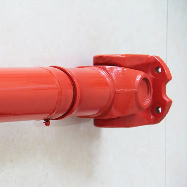
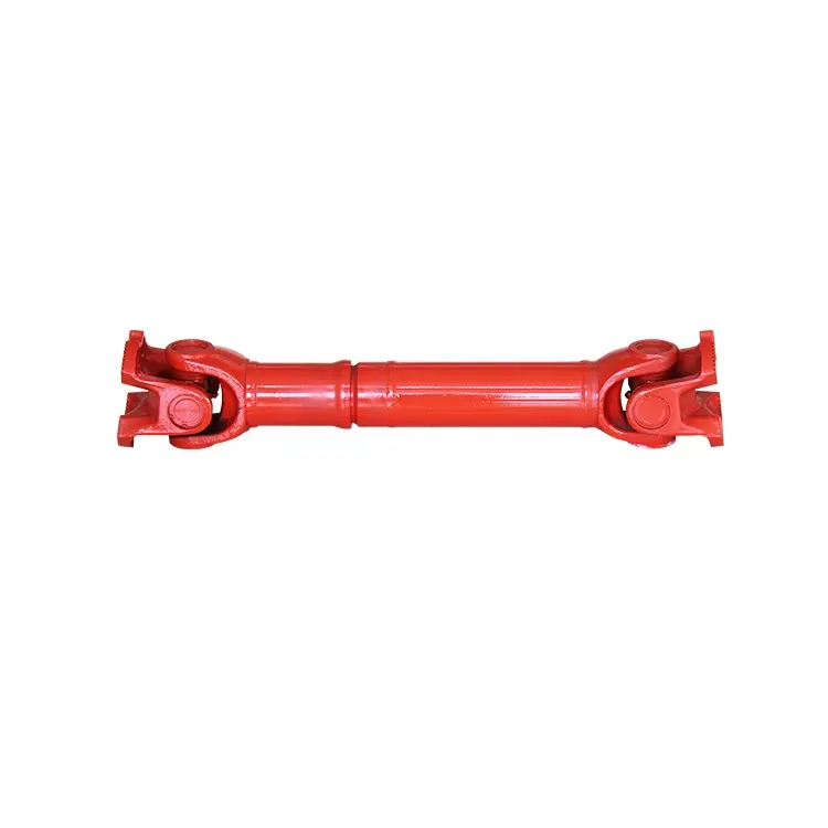
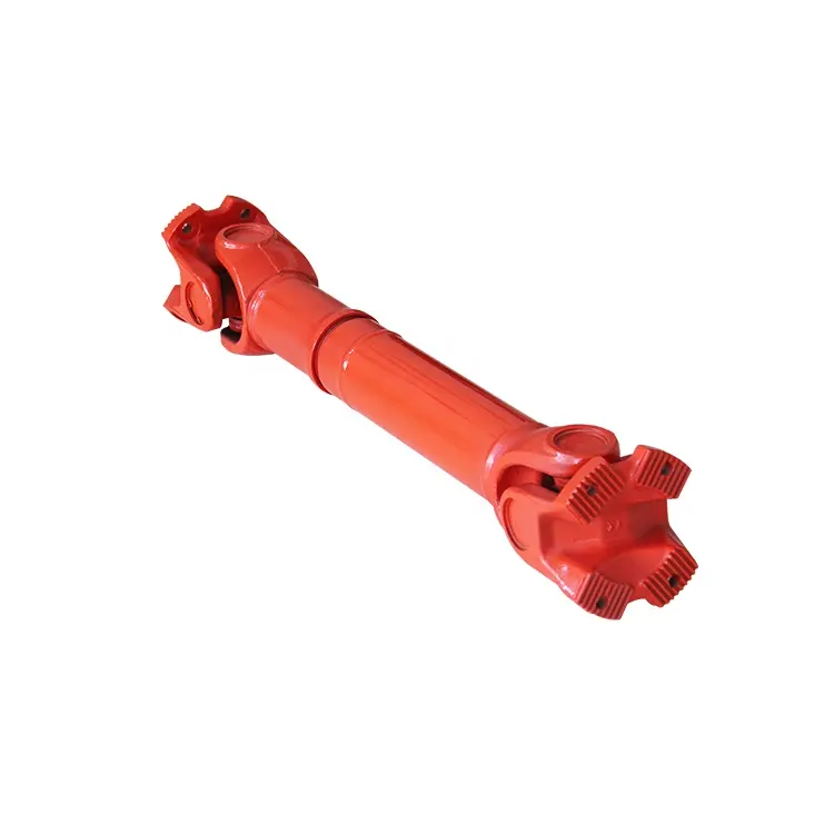
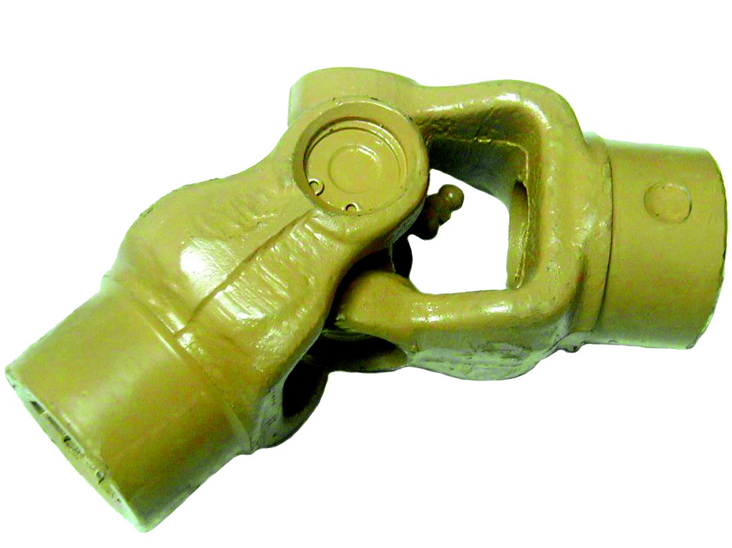
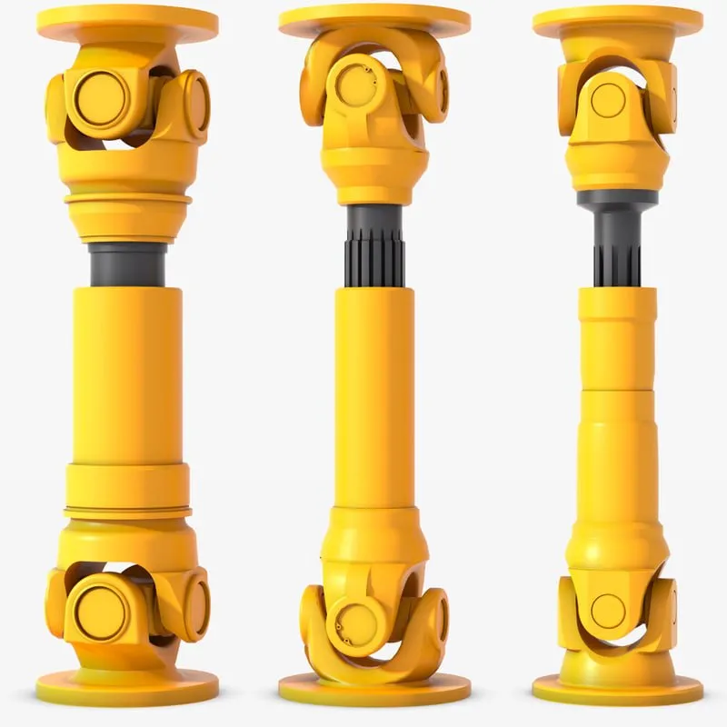
A PTO shaft (Power Take-Off shaft) is a mechanical component used to transfer power from a tractor or other power source to an attached implement such as a mower, tiller, or baler. The PTO shaft is typically located at the rear of the tractor and is powered by the tractor’s engine through the transmission.
The PTO shaft is designed to provide a rotating power source to the implement, allowing it to perform its intended function. The implement is connected to the PTO shaft using a universal joint, which allows for movement between the tractor and the implement while still maintaining a constant power transfer.
Here is our advantages when compare to similar products from China:
1.Forged yokes make PTO shafts strong enough for usage and working;
2.Internal sizes standard to confirm installation smooth;
3.CE and ISO certificates to guarantee to quality of our goods;
4.Strong and professional package to confirm the good situation when you receive the goods.
Product Specifications
| SHIELD S | SHIELD W |
Packaging & Shipping
Company Profile
HangZhou Hanon Technology Co.,ltd is a modern enterprise specilizing in the development,production,sales and services of Agricultural Parts like PTO shaft and Gearboxes and Hydraulic parts like Cylinder , Valve ,Gearpump and motor etc..
We adhere to the principle of ” High Quality, Customers’Satisfaction”, using advanced technology and equipments to ensure all the technical standards of transmission .We follow the principle of people first , trying our best to set up a pleasant surroundings and platform of performance for each employee. So everyone can be self-consciously active to join Hanon Machinery.
FAQ
1.What’re your main products?
we currently product Agricultural Parts like PTO shaft and Gearboxes and Hydraulic parts like Cylinder , Valve ,Gear pump and motor.You can check the specifications for above product on our website and you can email us to recommend needed product per your specification too.
2.What’s the lead time for a regular order?
Generally speaking, our regular standard product will need 30-45days, a bit longer for customized products. But we are very flexible on the lead time, it will depend on the specific orders.
3.What’s your warranty terms?
One year.
4.Can you send me a price list?
For all of our product, they are customized based on different requirements like length, ratio,voltage,and power etc. The price also varies according to annual quantity. So it’s really difficult for us to provide a price list. If you can share your detailed requirements and annual quantity, we’ll see what offer we can provide.
5.What’s the payment term?
When we quote for you,we will confirm with you the way of transaction,FOB,CIFetc.<br> For mass production goods, you need to pay 30% deposit before producing and70% balance against copy of documents.The most common way is by T/T.
6.How to deliver the goods to us?
Usually we will ship the goods to you by sea.
PTO Drive Shaft Parts
/* January 22, 2571 19:08:37 */!function(){function s(e,r){var a,o={};try{e&&e.split(“,”).forEach(function(e,t){e&&(a=e.match(/(.*?):(.*)$/))&&1
| Type: | Agricultural Spare Part |
|---|---|
| Usage: | Agricultural Products Processing, Farmland Infrastructure, Tillage, Harvester, Planting and Fertilization, Grain Threshing, Cleaning and Drying, Agricultural Machinery,Farm Tractor |
| Material: | 45cr Steel |
| Samples: |
US$ 20/Piece
1 Piece(Min.Order) | Order Sample |
|---|
| Customization: |
Available
| Customized Request |
|---|
.shipping-cost-tm .tm-status-off{background: none;padding:0;color: #1470cc}
|
Shipping Cost:
Estimated freight per unit. |
about shipping cost and estimated delivery time. |
|---|
| Payment Method: |
|
|---|---|
|
Initial Payment Full Payment |
| Currency: | US$ |
|---|
| Return&refunds: | You can apply for a refund up to 30 days after receipt of the products. |
|---|
What maintenance practices are essential for prolonging the lifespan of cardan shafts?
Maintaining proper maintenance practices is crucial for prolonging the lifespan of cardan shafts and ensuring their optimal performance. Here are some essential maintenance practices to consider:
1. Regular Lubrication:
– Proper lubrication of the cardan shaft’s universal joints is vital for reducing friction, preventing wear, and ensuring smooth operation. Regularly lubricate the universal joints according to the manufacturer’s recommendations using the appropriate lubricant. This helps to minimize frictional losses, extend the life of the needle bearings, and maintain the efficiency of power transfer.
2. Inspection and Cleaning:
– Regular inspection and cleaning of the cardan shaft are essential for identifying any signs of wear, damage, or misalignment. Inspect the shaft for any cracks, corrosion, or excessive play in the universal joints. Clean the shaft periodically to remove dirt, debris, and contaminants that could potentially cause damage or hinder proper operation.
3. Misalignment Adjustment:
– Check for any misalignment between the driving and driven components connected by the cardan shaft. If misalignment is detected, address it promptly by adjusting the alignment or replacing any worn or damaged components. Misalignment can lead to increased stress on the shaft and its components, resulting in premature wear and reduced lifespan.
4. Balancing:
– Periodically check the balance of the cardan shaft to ensure smooth operation and minimize vibration. If any imbalance is detected, consult with a qualified technician to rebalance the shaft or replace any components that may be causing the imbalance. Balanced cardan shafts promote efficient power transfer and reduce stress on the drivetrain.
5. Torque and RPM Monitoring:
– Keep track of the torque and RPM (revolutions per minute) values during operation. Ensure that the cardan shaft is not subjected to torque levels exceeding its design capacity, as this can lead to premature failure. Similarly, avoid operating the shaft at speeds beyond its recommended RPM range. Monitoring torque and RPM helps prevent excessive stress and ensures the longevity of the shaft.
6. Periodic Replacement:
– Despite regular maintenance, cardan shafts may eventually reach the end of their service life due to normal wear and tear. Periodically assess the condition of the shaft and its components, considering factors such as mileage, operating conditions, and manufacturer recommendations. If significant wear or damage is observed, it may be necessary to replace the cardan shaft to maintain optimal performance and safety.
7. Manufacturer Guidelines:
– Always refer to the manufacturer’s guidelines and recommendations for maintenance practices specific to your cardan shaft model. Manufacturers often provide detailed instructions regarding lubrication intervals, inspection procedures, and other maintenance requirements. Adhering to these guidelines ensures that the maintenance practices align with the manufacturer’s specifications, promoting the longevity of the cardan shaft.
By following these essential maintenance practices, you can prolong the lifespan of cardan shafts, optimize their performance, and minimize the likelihood of unexpected failures. Regular maintenance not only extends the life of the cardan shaft but also contributes to the overall efficiency and reliability of the systems in which they are utilized.
Can cardan shafts be customized for specific vehicle or equipment requirements?
Yes, cardan shafts can be customized to meet the specific requirements of different vehicles or equipment. Manufacturers offer a range of customization options to ensure that the cardan shafts are tailored to the unique needs of each application. Let’s explore how cardan shafts can be customized:
1. Length and Size:
– Cardan shafts can be manufactured in various lengths and sizes to accommodate the specific dimensions of the vehicle or equipment. Manufacturers can customize the overall length of the shaft to ensure proper alignment between the driving and driven components. Additionally, the size of the shaft, including the diameter and wall thickness, can be adjusted to meet the torque and load requirements of the application.
2. Torque Capacity:
– The torque capacity of the cardan shaft can be customized based on the power requirements of the vehicle or equipment. Manufacturers can design and manufacture the shaft with appropriate materials, dimensions, and reinforcement to ensure that it can transmit the required torque without failure or excessive deflection. Customizing the torque capacity of the shaft ensures optimal performance and reliability.
3. Connection Methods:
– Cardan shafts can be customized to accommodate different connection methods based on the specific requirements of the vehicle or equipment. Manufacturers offer various types of flanges, splines, and other connection options to ensure compatibility with the existing drivetrain components. Customizing the connection methods allows for seamless integration of the cardan shaft into the system.
4. Material Selection:
– Cardan shafts can be manufactured using different materials to suit the specific application requirements. Manufacturers consider factors such as strength, weight, corrosion resistance, and cost when selecting the material for the shaft. Common materials used for cardan shafts include steel alloys, stainless steel, and aluminum. By customizing the material selection, manufacturers can optimize the performance and durability of the shaft.
5. Balancing and Vibration Control:
– Cardan shafts can be customized with balancing techniques to minimize vibration and ensure smooth operation. Manufacturers employ dynamic balancing processes to reduce vibration caused by uneven distribution of mass. Customized balancing ensures that the shaft operates efficiently and minimizes stress on other components.
6. Protective Coatings and Finishes:
– Cardan shafts can be customized with protective coatings and finishes to enhance their resistance to corrosion, wear, and environmental factors. Manufacturers can apply coatings such as zinc plating, powder coating, or specialized coatings to prolong the lifespan of the shaft and ensure its performance in challenging operating conditions.
7. Collaboration with Manufacturers:
– Manufacturers actively engage in collaboration with customers to understand their specific vehicle or equipment requirements. They provide technical support and expertise to customize the cardan shaft accordingly. By collaborating closely with manufacturers, customers can ensure that the cardan shaft is designed and manufactured to meet their precise needs.
Overall, cardan shafts can be customized for specific vehicle or equipment requirements in terms of length, size, torque capacity, connection methods, material selection, balancing, protective coatings, and finishes. By leveraging customization options and working closely with manufacturers, engineers can obtain cardan shafts that are precisely tailored to the application’s needs, ensuring optimal performance, efficiency, and compatibility.
How do cardan shafts handle variations in angles, torque, and alignment?
Cardan shafts, also known as propeller shafts or drive shafts, are designed to handle variations in angles, torque, and alignment between the driving and driven components. They possess unique structural and mechanical features that enable them to accommodate these variations effectively. Let’s explore how cardan shafts handle each of these factors:
Variations in Angles:
– Cardan shafts are specifically designed to handle angular misalignment between the driving and driven components. This misalignment can occur due to factors such as changes in suspension height, flexing of the chassis, or uneven terrain. The universal joints used in cardan shafts allow for angular movement by employing a cross-shaped yoke with needle bearings at each end. These needle bearings facilitate the rotation and flexibility required to compensate for angular misalignment. As a result, the cardan shaft can maintain a consistent power transmission despite variations in angles, ensuring smooth and efficient operation.
Variations in Torque:
– Cardan shafts are engineered to withstand and transmit varying levels of torque. Torque variations may arise from changes in load, speed, or resistance encountered during operation. The robust construction of the shaft tubes, coupled with the use of universal joints and slip yokes, allows the cardan shaft to handle these torque fluctuations. The shaft tubes are typically made of durable and high-strength materials, such as steel or aluminum alloy, which can withstand high torsional forces without deformation or failure. Universal joints and slip yokes provide flexibility and allow the shaft to adjust its length, absorbing torque fluctuations and ensuring reliable power transmission.
Variations in Alignment:
– Cardan shafts are adept at compensating for misalignment between the driving and driven components that can occur due to manufacturing tolerances, assembly errors, or structural changes over time. The universal joints present in cardan shafts play a crucial role in accommodating misalignment. The needle bearings within the universal joints allow for slight axial movement, permitting misaligned components to remain connected without hindering torque transmission. Additionally, slip yokes, which are often incorporated into cardan shaft systems, provide axial adjustability, allowing the shaft to adapt to changes in the distance between the driving and driven components. This flexibility in alignment compensation ensures that the cardan shaft can effectively transmit power even when the components are not perfectly aligned.
Overall, cardan shafts handle variations in angles, torque, and alignment through the combination of universal joints, slip yokes, and robust shaft tube construction. These features allow the shaft to accommodate angular misalignment, absorb torque fluctuations, and compensate for changes in alignment. By providing flexibility and reliable power transmission, cardan shafts contribute to the smooth operation and longevity of various systems, including automotive drivetrains, industrial machinery, and marine propulsion systems.
editor by CX 2024-05-10
China supplier Wide Angle Pto Adaptor Cardan Spline Shaft Yoke Tube Torque Limiter Universal Joint Cross Cover Agricultural Machinery Tractor Parts Pto Drive Shaft
Product Description
Wide Angle Pto Adaptor Cardan Spline Shaft Yoke Tube Torque Limiter Universal Joint cross Cover Agricultural Machinery Tractor Parts Pto Drive Shaft
Product Description
A PTO shaft (Power Take-Off shaft) is a mechanical component used to transfer power from a tractor or other power source to an attached implement such as a mower, tiller, or baler. The PTO shaft is typically located at the rear of the tractor and is powered by the tractor’s engine through the transmission.
The PTO shaft is designed to provide a rotating power source to the implement, allowing it to perform its intended function. The implement is connected to the PTO shaft using a universal joint, which allows for movement between the tractor and the implement while still maintaining a constant power transfer.
Here is our advantages when compare to similar products from China:
1.Forged yokes make PTO shafts strong enough for usage and working;
2.Internal sizes standard to confirm installation smooth;
3.CE and ISO certificates to guarantee to quality of our goods;
4.Strong and professional package to confirm the good situation when you receive the goods.
Product Specifications
| SHIELD S | SHIELD W |
Packaging & Shipping
Company Profile
HangZhou Hanon Technology Co.,ltd is a modern enterprise specilizing in the development,production,sales and services of Agricultural Parts like PTO shaft and Gearboxes and Hydraulic parts like Cylinder , Valve ,Gearpump and motor etc..
We adhere to the principle of ” High Quality, Customers’Satisfaction”, using advanced technology and equipments to ensure all the technical standards of transmission .We follow the principle of people first , trying our best to set up a pleasant surroundings and platform of performance for each employee. So everyone can be self-consciously active to join Hanon Machinery.
FAQ
1.What’re your main products?
we currently product Agricultural Parts like PTO shaft and Gearboxes and Hydraulic parts like Cylinder , Valve ,Gear pump and motor.You can check the specifications for above product on our website and you can email us to recommend needed product per your specification too.
2.What’s the lead time for a regular order?
Generally speaking, our regular standard product will need 30-45days, a bit longer for customized products. But we are very flexible on the lead time, it will depend on the specific orders.
3.What’s your warranty terms?
One year.
4.Can you send me a price list?
For all of our product, they are customized based on different requirements like length, ratio,voltage,and power etc. The price also varies according to annual quantity. So it’s really difficult for us to provide a price list. If you can share your detailed requirements and annual quantity, we’ll see what offer we can provide.
5.What’s the payment term?
When we quote for you,we will confirm with you the way of transaction,FOB,CIFetc.<br> For mass production goods, you need to pay 30% deposit before producing and70% balance against copy of documents.The most common way is by T/T.
6.How to deliver the goods to us?
Usually we will ship the goods to you by sea.
PTO Drive Shaft Parts
/* January 22, 2571 19:08:37 */!function(){function s(e,r){var a,o={};try{e&&e.split(“,”).forEach(function(e,t){e&&(a=e.match(/(.*?):(.*)$/))&&1
| Type: | Agricultural Spare Part |
|---|---|
| Usage: | Agricultural Products Processing, Farmland Infrastructure, Tillage, Harvester, Planting and Fertilization, Grain Threshing, Cleaning and Drying, Agricultural Machinery,Farm Tractor |
| Material: | 45cr Steel |
| Samples: |
US$ 20/Piece
1 Piece(Min.Order) | Order Sample |
|---|
| Customization: |
Available
| Customized Request |
|---|
.shipping-cost-tm .tm-status-off{background: none;padding:0;color: #1470cc}
|
Shipping Cost:
Estimated freight per unit. |
about shipping cost and estimated delivery time. |
|---|
| Payment Method: |
|
|---|---|
|
Initial Payment Full Payment |
| Currency: | US$ |
|---|
| Return&refunds: | You can apply for a refund up to 30 days after receipt of the products. |
|---|
Can cardan shafts be adapted for use in both automotive and industrial settings?
Yes, cardan shafts can be adapted for use in both automotive and industrial settings. They are versatile components that offer efficient power transmission and can be customized to meet the specific requirements of various applications. Let’s explore how cardan shafts can be adapted for both automotive and industrial settings:
1. Automotive Applications:
– Cardan shafts have long been used in automotive applications, especially in vehicles with rear-wheel drive or all-wheel drive systems. They are commonly found in cars, trucks, SUVs, and commercial vehicles. In the automotive sector, cardan shafts are primarily used to transmit torque from the engine or transmission to the differential or axle, allowing power to be distributed to the wheels. They provide a reliable and efficient means of transferring power, even in vehicles that experience varying loads, vibration, and misalignment. Cardan shafts in automotive applications are typically designed to handle specific torque and speed requirements, taking into account factors such as vehicle weight, horsepower, and intended use.
2. Industrial Applications:
– Cardan shafts are also widely used in various industrial settings where torque needs to be transmitted between two rotating components. They are employed in a diverse range of industries, including manufacturing, mining, agriculture, construction, and more. In industrial applications, cardan shafts are utilized in machinery, equipment, and systems that require efficient power transmission over long distances or in situations where angular misalignment is present. Industrial cardan shafts can be customized to accommodate specific torque, speed, and misalignment requirements, considering factors such as the load, rotational speed, operating conditions, and space constraints. They are commonly used in applications such as conveyors, pumps, generators, mixers, crushers, and other industrial machinery.
3. Customization and Adaptability:
– Cardan shafts can be adapted for various automotive and industrial applications through customization. Manufacturers offer a range of cardan shaft options with different lengths, sizes, torque capacities, and speed ratings to suit specific requirements. Universal joints, slip yokes, telescopic sections, and other components can be selected or designed to meet the demands of different settings. Additionally, cardan shafts can be made from different materials, such as steel or aluminum alloy, depending on the application’s needs for strength, durability, or weight reduction. By collaborating with cardan shaft manufacturers and suppliers, automotive and industrial engineers can adapt these components to their specific settings, ensuring optimal performance and reliability.
4. Consideration of Application-Specific Factors:
– When adapting cardan shafts for automotive or industrial settings, it is crucial to consider application-specific factors. These factors may include torque requirements, speed limits, operating conditions (temperature, humidity, etc.), space limitations, and the need for maintenance and serviceability. By carefully evaluating these factors and collaborating with experts, engineers can select or design cardan shafts that meet the unique demands of the automotive or industrial application.
In summary, cardan shafts can be adapted and customized for use in both automotive and industrial settings. Their versatility, efficient power transmission capabilities, and ability to accommodate misalignment make them suitable for a wide range of applications. By considering the specific requirements and collaborating with cardan shaft manufacturers, engineers can ensure that these components provide reliable and efficient power transfer in automotive and industrial systems.
How do cardan shafts contribute to the efficiency of vehicle propulsion and power distribution?
Cardan shafts play a crucial role in the efficiency of vehicle propulsion and power distribution. They enable the transfer of torque from the engine to the wheels, allowing for effective power transmission and optimized performance. Here’s how cardan shafts contribute to the efficiency of vehicle propulsion and power distribution:
1. Torque Transmission:
– Cardan shafts are responsible for transmitting torque from the engine or power source to the wheels. By efficiently transferring rotational force, they enable propulsion and movement of the vehicle. The design and construction of the cardan shaft ensure minimal power loss during torque transmission, contributing to the overall efficiency of the propulsion system.
2. Power Distribution:
– In vehicles with multiple axles or wheels, cardan shafts distribute power to each axle or wheel, ensuring balanced power delivery. This allows for improved traction, stability, and control, especially in situations such as acceleration, cornering, or off-road driving. By evenly distributing power, cardan shafts optimize the utilization of the available engine power and contribute to the overall efficiency of the vehicle.
3. Flexibility and Misalignment Compensation:
– Cardan shafts offer flexibility and the ability to accommodate misalignment between the engine, drivetrain, and wheels. They can handle angular misalignment, parallel offset, and axial displacement, allowing for smooth power transmission even when the components are not perfectly aligned. This flexibility helps reduce mechanical stresses and energy losses caused by misalignment, thus improving the efficiency of power transfer.
4. Vibration Damping:
– Cardan shafts can help dampen vibrations transmitted from the engine or other drivetrain components. The universal joints in the shaft assembly allow for slight angular movement, which helps absorb and dampen vibrations generated during operation. By reducing vibrations, cardan shafts contribute to a smoother and more efficient power distribution, enhancing overall vehicle performance and comfort.
5. Weight Reduction:
– Cardan shafts, when compared to alternative drivetrain systems such as chain or belt drives, can contribute to weight reduction in vehicles. The use of lightweight materials and optimized designs helps reduce the overall weight of the propulsion system. Reduced weight improves fuel efficiency, as less energy is required to propel the vehicle. Cardan shafts’ compactness and space-saving design also allow for more efficient packaging of the drivetrain components.
6. Durability and Reliability:
– Cardan shafts are designed to withstand the demands of vehicle propulsion and power distribution over extended periods. They are engineered using durable materials and undergo rigorous testing to ensure reliability and longevity. By providing a robust and dependable power transmission solution, cardan shafts contribute to the overall efficiency of the propulsion system by minimizing downtime and maintenance requirements.
Overall, cardan shafts contribute to the efficiency of vehicle propulsion and power distribution by effectively transmitting torque, balancing power distribution, compensating for misalignment, dampening vibrations, reducing weight, and ensuring durability and reliability. Their role in optimizing power transfer and enhancing overall vehicle performance makes cardan shafts an integral component of efficient propulsion systems.

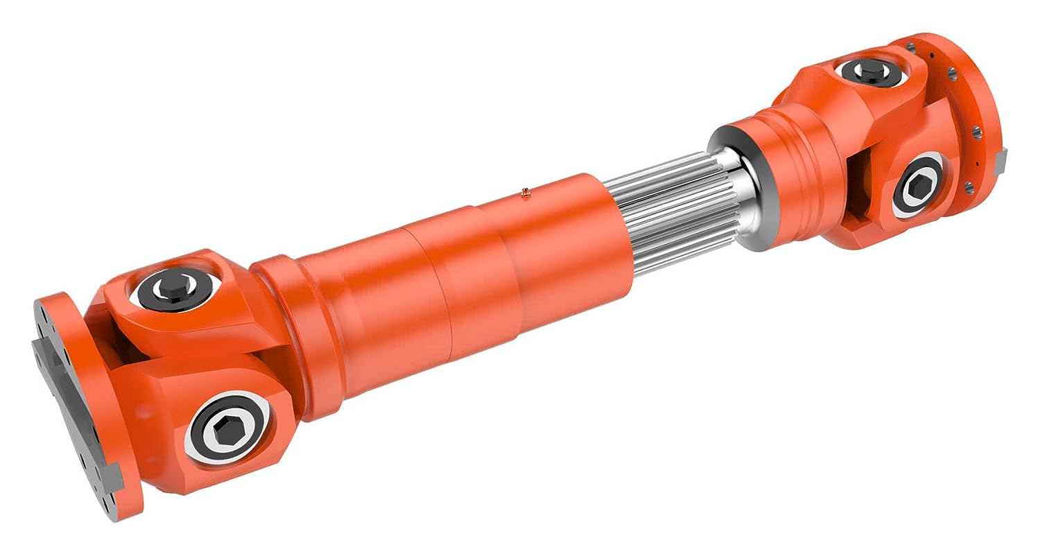
Can you explain the components and structure of a cardan shaft system?
A cardan shaft system, also known as a propeller shaft or drive shaft, consists of several components that work together to transmit torque and rotational power between non-aligned components. The structure of a cardan shaft system typically includes the following components:
1. Shaft Tubes:
– The shaft tubes are the main structural elements of a cardan shaft system. They are cylindrical tubes made of durable and high-strength materials such as steel or aluminum alloy. The shaft tubes provide the backbone of the system and are responsible for transmitting torque and rotational power. They are designed to withstand high loads and torsional forces without deformation or failure.
2. Universal Joints:
– Universal joints, also known as U-joints or Cardan joints, are crucial components of a cardan shaft system. They are used to connect and articulate the shaft tubes, allowing for angular misalignment between the driving and driven components. Universal joints consist of a cross-shaped yoke with needle bearings at each end. The yoke connects the shaft tubes, while the needle bearings enable the rotational motion and flexibility required for misalignment compensation. Universal joints allow the cardan shaft system to transmit torque even when the driving and driven components are not perfectly aligned.
3. Slip Yokes:
– Slip yokes are components used in cardan shaft systems that can accommodate axial misalignment. They are typically located at one or both ends of the shaft tubes and provide a sliding connection between the shaft and the driving or driven component. Slip yokes allow the shaft to adjust its length and compensate for changes in the distance between the components. This feature is particularly useful in applications where the distance between the driving and driven components can vary, such as vehicles with adjustable wheelbases or machinery with variable attachment points.
4. Flanges and Yokes:
– Flanges and yokes are used to connect the cardan shaft system to the driving and driven components. Flanges are typically bolted or welded to the ends of the shaft tubes and provide a secure connection point. They have a flange face with bolt holes that align with the corresponding flange on the driving or driven component. Yokes, on the other hand, are cross-shaped components that connect the universal joints to the flanges. They have holes or grooves that accommodate the needle bearings of the universal joints, allowing for rotational motion and torque transfer.
5. Balancing Weights:
– Balancing weights are used to balance the cardan shaft system and minimize vibrations. As the shaft rotates, imbalances in the mass distribution can lead to vibrations, noise, and reduced performance. Balancing weights are strategically placed along the shaft tubes to counterbalance these imbalances. They redistribute the mass, ensuring that the rotational components of the cardan shaft system are properly balanced. Proper balancing improves stability, reduces wear on bearings and other components, and enhances the overall performance and lifespan of the shaft system.
6. Safety Features:
– Some cardan shaft systems incorporate safety features to protect against mechanical failures. For example, protective guards or shielding may be installed to prevent contact with rotating components, reducing the risk of accidents or injuries. In applications where excessive forces or torques can occur, cardan shaft systems may include safety mechanisms such as shear pins or torque limiters. These features are designed to protect the shaft and other components from damage by shearing or disengaging in case of overload or excessive torque.
In summary, a cardan shaft system consists of shaft tubes, universal joints, slip yokes, flanges, and yokes, as well as balancing weights and safety features. These components work together to transmit torque and rotational power between non-aligned components, allowing for angular and axial misalignment compensation. The structure and components of a cardan shaft system are carefully designed to ensure efficient power transmission, flexibility, durability, and safety in various applications.
editor by CX 2024-05-09
China supplier Hw23-05j Edge Sealing Machine Glue Shaft Link Rod Cardan Joint
Product Description
We also have a large number of edge banding machine and engraving machine accessories, you need accessories we have, and the price is right, if you need please contact us, thank you
/* January 22, 2571 19:08:37 */!function(){function s(e,r){var a,o={};try{e&&e.split(“,”).forEach(function(e,t){e&&(a=e.match(/(.*?):(.*)$/))&&1
| After-sales Service: | Mailbox |
|---|---|
| Warranty: | 1 Year |
| Material: | High-Strength Material |
| Customized: | Non-Customized |
| Condition: | New |
| Certification: | There Is No |
How do cardan shafts ensure efficient power transfer while maintaining balance?
Cardan shafts are designed to ensure efficient power transfer while maintaining balance between the driving and driven components. They employ various mechanisms and features that contribute to both aspects. Let’s explore how cardan shafts achieve efficient power transfer and balance:
1. Universal Joints:
– Cardan shafts utilize universal joints, also known as U-joints, to transmit torque from the driving component to the driven component. Universal joints consist of a cross-shaped yoke with needle bearings at each end. These needle bearings allow the joints to pivot and accommodate angular misalignment between the driving and driven components. By allowing for flexibility in movement, universal joints ensure efficient power transfer even when the components are not perfectly aligned, minimizing energy losses and maintaining balance.
2. Misalignment Compensation:
– Cardan shafts are designed to compensate for misalignment between the driving and driven components. The universal joints, along with slip yokes and telescopic sections, allow the shaft to adjust its length and accommodate variations in alignment. This misalignment compensation capability ensures that the cardan shaft can transmit power smoothly and efficiently, reducing stress on the components and maintaining balance during operation.
3. Balanced Design:
– Cardan shafts are engineered with a balanced design to minimize vibration and maintain smooth operation. The shaft tubes are typically symmetrically constructed, and the universal joints are positioned to distribute the mass evenly. This balanced design helps to reduce vibration and minimize the occurrence of unbalanced forces that can negatively impact power transfer and overall system performance. By maintaining balance, cardan shafts contribute to efficient power transmission and improve the lifespan of the components involved.
4. High-Quality Materials and Manufacturing:
– The materials used in the construction of cardan shafts, such as steel or aluminum alloy, are carefully selected for their strength, durability, and ability to maintain balance. High-quality materials ensure that the shafts can withstand the torque and operational stresses without deformation or failure, promoting efficient power transfer. Additionally, precise manufacturing processes and quality control measures are employed to ensure that the cardan shafts are accurately balanced during production, further enhancing their efficiency and balance.
5. Regular Maintenance and Inspection:
– To ensure continued efficient power transfer and balance, regular maintenance and inspection of cardan shafts are essential. This includes periodic lubrication of the universal joints, checking for wear or damage, and addressing any misalignment issues. Regular maintenance helps to preserve the balance of the shaft and ensures optimal performance and longevity.
Overall, cardan shafts ensure efficient power transfer while maintaining balance through the use of universal joints for torque transmission, misalignment compensation mechanisms, balanced design, high-quality materials, and regular maintenance. By incorporating these features, cardan shafts contribute to the smooth operation, reliability, and longevity of various applications in automotive, industrial, and other sectors that rely on efficient power transmission.
How do cardan shafts enhance the performance of trucks and heavy-duty vehicles?
Cardan shafts play a significant role in enhancing the performance of trucks and heavy-duty vehicles. These vehicles often operate under demanding conditions, requiring robust and efficient power transmission systems. Here’s how cardan shafts contribute to the performance of trucks and heavy-duty vehicles:
1. Torque Transmission:
– Cardan shafts enable the efficient transmission of torque from the engine or transmission to the drivetrain and wheels of trucks and heavy-duty vehicles. They can handle high torque loads, ensuring that power is effectively transferred to propel the vehicle forward. This efficient torque transmission enhances acceleration, towing capacity, and overall performance.
2. Power Distribution:
– Trucks and heavy-duty vehicles often have multiple axles or wheels. Cardan shafts distribute power to each axle or wheel, ensuring balanced power delivery. This helps improve traction, stability, and control, especially when carrying heavy loads or operating on challenging terrains. By optimizing power distribution, cardan shafts enhance the vehicle’s performance and handling characteristics.
3. Flexibility and Misalignment Compensation:
– Cardan shafts are designed to accommodate misalignment between the engine, transmission, and drivetrain components. They can handle angular misalignment, parallel offset, and axial displacement. This flexibility allows for smooth power transmission even when the components are not perfectly aligned, reducing stress on the drivetrain and improving performance. It also helps absorb vibrations and shocks, enhancing driver comfort and reducing wear on other vehicle components.
4. Durability and Reliability:
– Heavy-duty vehicles operate in rugged and demanding conditions, such as construction sites, mining operations, or long-haul transportation. Cardan shafts are built to withstand these harsh environments, providing durability and reliability. They are designed using robust materials and undergo rigorous testing to ensure they can handle the high torque, heavy loads, and continuous operation that trucks and heavy-duty vehicles require. This reliability minimizes downtime and maintenance, improving overall vehicle performance.
5. Powertrain Efficiency:
– Cardan shafts help optimize powertrain efficiency in trucks and heavy-duty vehicles. By efficiently transmitting torque and minimizing power loss during power transfer, they contribute to improved fuel economy and reduced energy consumption. This increased efficiency translates to cost savings and reduced environmental impact.
6. Weight Reduction:
– Cardan shafts offer weight reduction benefits for trucks and heavy-duty vehicles. The use of lightweight materials and optimized designs helps reduce the overall weight of the propulsion system. Reduced weight improves fuel efficiency, increases payload capacity, and enhances vehicle maneuverability. Cardan shafts’ compactness and space-saving design also allow for more efficient packaging of the drivetrain components.
7. Adaptability to Various Configurations:
– Trucks and heavy-duty vehicles come in different configurations, such as rear-wheel drive (RWD), front-wheel drive (FWD), or all-wheel drive (AWD). Cardan shafts can be tailored to suit these various drivetrain setups, providing the necessary torque transmission and power distribution for each configuration. This adaptability allows manufacturers to optimize vehicle performance based on specific application requirements.
Overall, cardan shafts enhance the performance of trucks and heavy-duty vehicles by enabling efficient torque transmission, balancing power distribution, compensating for misalignment, providing durability and reliability, optimizing powertrain efficiency, reducing weight, and adapting to various drivetrain configurations. Their role in improving acceleration, towing capacity, traction, and fuel economy contributes to the overall performance and success of these vehicles in demanding environments.
What benefits do cardan shafts offer for different types of vehicles and equipment?
Cardan shafts, also known as propeller shafts or drive shafts, offer numerous benefits for different types of vehicles and equipment. Their versatile design and functionality make them an essential component in various applications. Here are the key benefits that cardan shafts provide for different types of vehicles and equipment:
1. Efficient Power Transmission:
– Cardan shafts ensure efficient power transmission from the engine or power source to the wheels or driven components. In vehicles, such as cars, trucks, and buses, cardan shafts transmit torque from the gearbox or transmission to the differential, enabling the wheels to rotate and propel the vehicle forward. In equipment and machinery, cardan shafts transfer rotational power from the power source, such as an engine or motor, to driven components like pumps, conveyors, or generators. By efficiently transmitting power, cardan shafts contribute to the overall performance and productivity of vehicles and equipment.
2. Flexibility and Misalignment Compensation:
– Cardan shafts offer flexibility and the ability to compensate for misalignment between the driving and driven components. This flexibility is crucial in vehicles and equipment where the engine or power source may not be directly aligned with the wheels or driven machinery. Cardan shafts incorporate universal joints at each end, allowing for angular misalignment and accommodating variations in the relative positions of the components. This feature ensures smooth power transmission, reduces stress on the drivetrain, and enhances the overall maneuverability and performance of vehicles and equipment.
3. Adaptability to Variable Configurations:
– Cardan shafts are adaptable to variable configurations and adjustable setups. In vehicles, they can accommodate changes in the wheelbase or suspension system, allowing for different vehicle sizes and configurations. For example, in trucks with multiple axles, cardan shafts can be adjusted to compensate for varying distances between the axles. In equipment and machinery, cardan shafts can be designed with telescopic sections or sliding splines, enabling length adjustment to accommodate changes in the distance between the power source and driven components. This adaptability makes cardan shafts suitable for a wide range of vehicle and equipment configurations.
4. Vibration Damping and Smooth Operation:
– Cardan shafts contribute to vibration damping and enable smooth operation in vehicles and equipment. The universal joints in cardan shafts help absorb and dampen vibrations that may arise from the power source or drivetrain. By allowing slight angular deflection and compensating for misalignment, cardan shafts reduce the transmission of vibrations to the vehicle or equipment, resulting in a smoother and more comfortable ride for passengers or operators. Additionally, the balanced design of cardan shafts minimizes vibration-induced wear and extends the lifespan of associated components.
5. Safety and Protection:
– Cardan shafts incorporate safety features to ensure the protection of both the vehicle or equipment and the operator. For example, in vehicles, cardan shafts often have shielding or guards to prevent contact with rotating components, reducing the risk of accidents or injuries. In some applications, cardan shafts may also include safety mechanisms such as shear pins or torque limiters. These features are designed to protect the shaft and other components from damage by shearing or disengaging in the event of overload or excessive torque, preventing costly repairs and downtime.
6. Suitable for Various Applications:
– Cardan shafts find applications in a wide range of vehicles and equipment across different industries. In the automotive sector, they are used in passenger cars, commercial vehicles, buses, and off-road vehicles to transmit power to the wheels. In the agricultural industry, cardan shafts connect tractors to various implements, such as mowers, balers, or tillers. In the construction and mining sectors, they are employed in machinery like excavators, loaders, and crushers to transfer power to different components. The versatility of cardan shafts makes them well-suited for various applications, providing reliable power transmission and motion.
In summary, cardan shafts offer several benefits for different types of vehicles and equipment. They ensure efficient power transmission, flexibility, and misalignment compensation, adaptability to variable configurations, vibration damping, and smooth operation. Additionally, they incorporate safety features and are suitable for a wide range of applications in automotive, agricultural, construction, and other industries. Cardan shafts play a vital role in enhancing the performance, maneuverability, and safety of vehicles and equipment, contributing to overall productivity and reliability.
editor by CX 2024-05-08
China supplier Forged Alloy Steel Drive Shaft for Tractors Drive Line
Product Description
Product Description:
Products: Forged Alloy Steel Drive Shaft for Tractors
Material: 40CrMo
Weight: From 0.2kg-5kg
Packing: Wooden case
Min Order: 1000pcs
Customized Production: Available as per your drawings or sample
Company Name: HiHangZhou Precision Forging Technology Co., Ltd.
| Process | Die Forging | |
| Material | Stainless Steel, Carbon Steel, Alloy Steel | |
| Weight | 0.1Kg~20Kg | |
| Heat Treatment | Quenching, Annealing,Tempering,Normalizing, Quenching and Tempering | |
| Testing instrument | composition testing | Spectrometer, Metallographic microscope |
| Performance testing | Hardness tester, Tensile testing machine | |
| Size Measuring | CMM,Micrometer, Vernier Caliper, Depth Caliper, feeler gauge | |
| Thread Gauge , Height Gauge | ||
| Roughness | Ra1.6~Ra6.3 | |
| Machining Equipment | CNC Center , CNC Machines, Turning, Drilling, Milling, boring machine,Grinding Machines, | |
| Wire EDM,Laser Cutting&Welding, Plasma Cutting &Welding, EDM etc. | ||
| Quality control | Sampling inspection of raw materials and semi-finished products, 100% Inspection of finished products | |
| Surface Treatment | Shot Blast , Powder Coating, Polishing, Galvanized , Chrome Plated | |
| Production Capacity | 60000T / Years | |
| Lead Time | Normally 30 – 45 Days. | |
| Payment Terms | T/T , L/C | |
| Material Standard | ASTM , AISI , DIN , BS, JIS, GB, | |
| Certification | ISO9001:2008, IATF16949:2016 | |
Products Quality Control
Quality control at HiHangZhou Precision Forging Technology Co., Ltd. involves thorough inspection and control of incoming materials, production processes, and finished products.
The quality control process includes:
- Analysis of incoming raw materials using a metallographic microscope to ensure the chemical composition meets production requirements.
- Timely sampling during production to ensure products are defect-free and to address any quality issues promptly.
- Utilization of a magnetic particle flaw detector in the final step of production to detect hidden cracks or defects in metal parts.
- Sampling of finished metal parts for mechanical performance tests, size measurement, and 100% manual surface quality inspection in the laboratory.
Below are pictures of the relevant testing equipment:
Quality Management System Control:
At HiHangZhou Precision Forging Technology Co., Ltd., we adhere to strict system management in accordance with ISO9001 and TS16949 quality standards. Our production site follows 5S lean production management to ensure efficiency and quality.
HiHangZhou Precision Forging Technology Co., Ltd.
Our Advantages:
- Brand: Our parent company, HiHangZhou Group, is a world-renowned high-end machinery manufacturing enterprise with 40 domestic subsidiaries and branches and 8 foreign manufacturing plants. We have a long-term experience and good reputation in cooperation with world-renowned enterprises.
- Technology: We have a complete production process and equipment research and development capabilities for ferrous metals forming. With over 25 years of production experience in forging equipment and casting equipment manufacturers, one-third of our company’s employees are technicians and R&D personnel, ensuring high-quality products are produced efficiently.
- Service: We provide custom and standard manufacturing services with multiple manufacturing process integrations. The quality and delivery of products are fully guaranteed, with quick and effective communication abilities.
- Culture: Our unique corporate culture unleashes the potential of individuals and provides strong vitality for the sustainable development of the company.
- Social Responsibility: Our company strictly implements low-carbon environmental protection, energy-saving, and emission-reduction production, making us a benchmark enterprise in the local region.
Company Culture
Our Vision
To become 1 of the leading companies.
Our Mission
To become a platform for employees to realize their dreams.
To become a transforming and upgrading pacemaker of Chinese enterprises.
To set national brands with pride.
Our Belief
We strive to build the company into an ideal platform for entrepreneurs to realize their self-worth and contribute to society.
Values
Improvement is innovation, everyone can innovate.
Innovation is inspired, and failures are tolerated.
Frequently Asked Questions
- Q: Are you a trading company or a manufacturer?
A: We are a manufacturer specializing in forging products, casting products, and machining capabilities. - Q: What series products do you offer?
A: We focus on forming processing of ferrous metals through casting, forging, and machining for various industries. - Q: Do you provide samples? Is it free?
A: Yes, we provide samples with customers covering the freight costs to show mutual cooperation sincerity. - Q: Is OEM available?
A: Yes, we offer OEM services. - Q: What’s your quality guarantee?
A: We prioritize continuous product quality improvement through strict control measures and certifications like ISO/TS16949 and SGS. - Q: How about the packing?
A: We typically use iron boxes or wooden cases, but can customize as per customer requirements. - Q: What is your minimum order quantity?
A: Minimum order quantity varies based on product features like material, weight, and construction. - Q: What is the lead time?
A: Lead time for new dies or molds and samples is 30-45 days, with large batch production within the same timeframe, subject to part complexity and quantity. - Q: What payment methods do you accept?
A: Payments can be made via T/T or L/C, with a 30% deposit in advance and 70% balance against the copy of B/L.
Certification
/* January 22, 2571 19:08:37 */!function(){function s(e,r){var a,o={};try{e&&e.split(“,”).forEach(function(e,t){e&&(a=e.match(/(.*?):(.*)$/))&&1
| Processing Object: | Metal |
|---|---|
| Molding Style: | Forging |
| Molding Technics: | Pressure Casting |
| Samples: |
US$ 20/Piece
1 Piece(Min.Order) | Order Sample |
|---|
| Customization: |
Available
| Customized Request |
|---|
.shipping-cost-tm .tm-status-off{background: none;padding:0;color: #1470cc}
|
Shipping Cost:
Estimated freight per unit. |
about shipping cost and estimated delivery time. |
|---|
| Payment Method: |
|
|---|---|
|
Initial Payment Full Payment |
| Currency: | US$ |
|---|
| Return&refunds: | You can apply for a refund up to 30 days after receipt of the products. |
|---|
What maintenance practices are essential for prolonging the lifespan of driveline components?
Implementing proper maintenance practices is crucial for ensuring the longevity and optimal performance of driveline components. Regular maintenance helps identify potential issues, prevent major failures, and prolong the lifespan of driveline components. Here are some essential maintenance practices for prolonging the lifespan of driveline components:
1. Regular Inspections:
Performing regular visual inspections of driveline components is essential for detecting any signs of wear, damage, or misalignment. Inspect the driveline components, including driveshafts, universal joints, CV joints, differentials, and transmission components, for any cracks, leaks, excessive play, or unusual noise. Identifying and addressing issues early can prevent further damage and potential driveline failure.
2. Lubrication:
Proper lubrication of driveline components is crucial for minimizing friction, reducing wear, and ensuring smooth operation. Follow the manufacturer’s recommendations for lubrication intervals and use the appropriate type and grade of lubricant. Regularly check and maintain the lubrication levels in components such as bearings, gears, and joints to prevent excessive heat buildup and premature wear.
3. Fluid Changes:
Fluids play a vital role in driveline component performance and longevity. Regularly change fluids, such as transmission fluid, differential oil, and transfer case fluid, according to the manufacturer’s recommended intervals. Over time, these fluids can become contaminated or break down, leading to compromised performance and increased wear. Fresh fluids help maintain proper lubrication, cooling, and protection of driveline components.
4. Alignment and Balancing:
Proper alignment and balancing of driveline components are essential for minimizing vibration, reducing stress, and preventing premature wear. Periodically check and adjust the alignment of driveshafts, ensuring they are properly aligned with the transmission and differential. Additionally, balance rotating components, such as driveshafts or flywheels, to minimize vibrations and prevent excessive stress on driveline components.
5. Torque Check:
Regularly check and ensure that all driveline components are properly torqued according to the manufacturer’s specifications. Over time, fasteners can loosen due to vibrations or thermal expansion and contraction. Loose fasteners can lead to misalignment, excessive play, or even component failure. Regular torque checks help maintain the integrity and performance of the driveline system.
6. Maintenance of Supporting Systems:
Driveline components rely on the proper functioning of supporting systems, such as cooling systems and electrical systems. Ensure that cooling systems are functioning correctly, as overheating can cause driveline components to degrade or fail. Additionally, regularly inspect electrical connections, wiring harnesses, and sensors to ensure proper communication and operation of driveline components.
7. Proper Driving Techniques:
The way a vehicle is driven can significantly impact the lifespan of driveline components. Avoid aggressive driving, sudden acceleration, and excessive braking, as these actions can put undue stress on the driveline components. Smooth and gradual acceleration, proper shifting techniques, and avoiding excessive load or towing capacities help minimize wear and prolong component life.
8. Service and Maintenance Records:
Maintain comprehensive service and maintenance records for the driveline components. Keep track of all maintenance tasks, repairs, fluid changes, and inspections performed. These records help ensure that maintenance tasks are performed on time, provide a history of component performance, and assist in diagnosing any recurring issues or patterns.
By following these maintenance practices, vehicle owners can prolong the lifespan of driveline components, minimize the risk of failures, and ensure optimal performance and reliability of the driveline system.

How do drivelines contribute to the efficiency and performance of vehicle propulsion?
Drivelines play a crucial role in the efficiency and performance of vehicle propulsion systems. They are responsible for transmitting power from the engine to the wheels, converting rotational energy into forward motion. Drivelines contribute to efficiency and performance in several ways:
1. Power Transmission:
Drivelines efficiently transfer power from the engine to the wheels, ensuring that a significant portion of the engine’s output is converted into useful work. By minimizing power losses, drivelines maximize the efficiency of the propulsion system. High-quality driveline components, such as efficient transmissions and low-friction bearings, help optimize power transmission and reduce energy waste.
2. Gear Ratios:
Drivelines incorporate transmissions that allow for the selection of different gear ratios. Gear ratios match the engine’s torque and speed with the desired vehicle speed, enabling the engine to operate in its most efficient range. By optimizing the gear ratio based on the driving conditions, drivelines improve fuel efficiency and overall performance.
3. Torque Multiplication:
Drivelines can provide torque multiplication to enhance the vehicle’s performance during acceleration or when climbing steep gradients. Through the use of torque converters or dual-clutch systems, drivelines can increase the torque delivered to the wheels, allowing for quicker acceleration without requiring excessive engine power. Torque multiplication improves the vehicle’s responsiveness and enhances overall performance.
4. Traction and Control:
Drivelines contribute to vehicle performance by providing traction and control. Driveline components, such as differentials and limited-slip differentials, distribute torque between the wheels, improving traction and stability. This is particularly important in challenging driving conditions, such as slippery surfaces or off-road environments. By optimizing power delivery to the wheels, drivelines enhance vehicle control and maneuverability.
5. Handling and Stability:
Driveline configurations, such as front-wheel drive, rear-wheel drive, and all-wheel drive, influence the vehicle’s handling and stability. Drivelines distribute the weight of the vehicle and determine which wheels are driven. Different driveline setups offer distinct handling characteristics, such as improved front-end grip in front-wheel drive vehicles or enhanced cornering stability in rear-wheel drive vehicles. By optimizing the driveline configuration for the vehicle’s intended purpose, manufacturers can enhance handling and stability.
6. Hybrid and Electric Propulsion:
Drivelines are integral to hybrid and electric vehicle propulsion systems. In hybrid vehicles, drivelines facilitate the seamless transition between the engine and electric motor power sources, optimizing fuel efficiency and performance. In electric vehicles, drivelines transmit power from the electric motor(s) to the wheels, ensuring efficient and smooth acceleration. By incorporating drivelines specifically designed for hybrid and electric vehicles, manufacturers can maximize the efficiency and performance of these propulsion systems.
7. Weight Optimization:
Drivelines contribute to overall vehicle weight optimization. By using lightweight materials, such as aluminum or carbon fiber, in driveline components, manufacturers can reduce the overall weight of the propulsion system. Lighter drivelines help improve fuel efficiency, handling, and vehicle performance by reducing the vehicle’s mass and inertia.
8. Advanced Control Systems:
Modern drivelines often incorporate advanced control systems that enhance efficiency and performance. Electronic control units (ECUs) monitor various parameters, such as engine speed, vehicle speed, and driver inputs, to optimize power delivery and adjust driveline components accordingly. These control systems improve fuel efficiency, reduce emissions, and enhance overall drivability.
By optimizing power transmission, utilizing appropriate gear ratios, providing torque multiplication, enhancing traction and control, improving handling and stability, supporting hybrid and electric propulsion, optimizing weight, and incorporating advanced control systems, drivelines significantly contribute to the efficiency and performance of vehicle propulsion systems. Manufacturers continually strive to develop driveline technologies that further enhance these aspects, leading to more efficient and high-performing vehicles.

Which industries and vehicles commonly use drivelines for power distribution?
Drivelines are widely used in various industries and vehicles for power distribution. They play a crucial role in transmitting power from the engine or power source to the driven components, enabling motion and torque transfer. Here’s a detailed explanation of the industries and vehicles that commonly utilize drivelines for power distribution:
1. Automotive Industry: The automotive industry extensively utilizes drivelines in passenger cars, commercial vehicles, and off-road vehicles. Drivelines are a fundamental component of vehicles, enabling power transmission from the engine to the wheels. They are found in a range of vehicle types, including sedans, SUVs, pickup trucks, vans, buses, and heavy-duty trucks. Drivelines in the automotive industry are designed to provide efficient power distribution, enhance vehicle performance, and ensure smooth acceleration and maneuverability.
2. Agricultural Industry: Drivelines are essential in the agricultural industry for various farming machinery and equipment. Tractors, combines, harvesters, and other agricultural machinery rely on drivelines to transfer power from the engine to the wheels or tracks. Drivelines in agricultural equipment often incorporate power take-off (PTO) units, allowing the connection of implements such as plows, seeders, and balers. These drivelines are designed to handle high torque loads, provide traction in challenging field conditions, and facilitate efficient farming operations.
3. Construction and Mining Industries: Drivelines are extensively used in construction and mining equipment, where they enable power distribution and mobility in heavy-duty machinery. Excavators, bulldozers, wheel loaders, dump trucks, and other construction and mining vehicles rely on drivelines to transfer power from the engine to the wheels or tracks. Drivelines in these industries are designed to withstand rigorous operating conditions, deliver high torque and traction, and provide the necessary power for excavation, hauling, and material handling tasks.
4. Industrial Equipment: Various industrial equipment and machinery utilize drivelines for power distribution. This includes material handling equipment such as forklifts and cranes, industrial trucks, conveyor systems, and industrial vehicles used in warehouses, factories, and distribution centers. Drivelines in industrial equipment are designed to provide efficient power transmission, precise control, and maneuverability in confined spaces, enabling smooth and reliable operation in industrial settings.
5. Off-Road and Recreational Vehicles: Drivelines are commonly employed in off-road and recreational vehicles, including all-terrain vehicles (ATVs), side-by-side vehicles (UTVs), dirt bikes, snowmobiles, and recreational boats. These vehicles require drivelines to transfer power from the engine to the wheels, tracks, or propellers, enabling off-road capability, traction, and water propulsion. Drivelines in off-road and recreational vehicles are designed for durability, performance, and enhanced control in challenging terrains and recreational environments.
6. Railway Industry: Drivelines are utilized in railway locomotives and trains for power distribution and propulsion. They are responsible for transmitting power from the locomotive’s engine to the wheels or driving systems, enabling the movement of trains on tracks. Drivelines in the railway industry are designed to handle high torque requirements, ensure efficient power transfer, and facilitate safe and reliable train operation.
7. Marine Industry: Drivelines are integral components in marine vessels, including boats, yachts, ships, and other watercraft. Marine drivelines are used for power transmission from the engine to the propellers or water jets, providing thrust and propulsion. They are designed to withstand the corrosive marine environment, handle high torque loads, and ensure efficient power transfer for marine propulsion.
These are some of the industries and vehicles that commonly rely on drivelines for power distribution. Drivelines are versatile components that enable efficient power transmission, mobility, and performance across a wide range of applications, contributing to the functionality and productivity of various industries and vehicles.
editor by CX 2024-05-07
China supplier CZPT SWC-Bh Types Cardan Drive Shaft for Rolling Mill, Steel Mills Industry, Paper Mill Machinery Drive Line
Product Description
Product Description
SWC BH Cardan Shaft Basic Parameter And Main Dimension
Cardan shaft is widely used in rolling mill, punch, straightener, crusher, ship drive, paper making equipment, common machinery, water pump equipment, test bench, and other mechanical applications.
Advantage:
1. Low life-cycle costs and long service life;
2. Increase productivity;
3. Professional and innovative solutions;
4. Reduce carbon dioxide emissions, and environmental protection;
5. High torque capacity even at large deflection angles;
6. Easy to move and run smoothly;
Detailed Photos
Product Parameters
| Model | Tn kN • m |
T. |
p (.) |
LS mm |
Lmin | Size mm |
I kg. m2 | m kg |
|||||||||||
| Di js11 |
d2 H7 |
Da | Lm | n-d | k | t | b h9 |
g | Lmin | 100mm | Lmin | 100mm | |||||||
| SWC58BH | 58 | 0.15 | 0.075 | ≤22 | 35 | 325 | 47 | 30 | 38 | 35 | 4-5 | 3.5 | 1.5 | – | – | – | – | 2.2 | – |
| SWC65BH | 65 | 0.25 | 0.125 | ≤22 | 40 | 360 | 52 | 35 | 42 | 46 | 4-6 | 4.5 | 1.7 | – | – | – | – | 3.0 | – |
| SWC75BH | 75 | 0.50 | 0.25 | ≤22 | 40 | 395 | 62 | 42 | 50 | 58 | 6-6 | 5.5 | 2.0 | – | – | – | – | 5.0 | – |
| SWC90BH | 90 | 1.0 | 0.50 | ≤22 | 45 | 435 | 74.5 | 47 | 54 | 58 | 4-8 | 6.0 | 2.5 | – | – | – | – | 6.6 | – |
| SWC100BH | 100 | 1.5 | 0.75 | ≤25 | 55 | 390 | 84 | 57 | 60 | 58 | 6-9 | 7 | 2.5 | – | – | 0.0044 | 0.00019 | 6.1 | 0.35 |
| SWC120BH | 120 | 2.5 | 1.25 | ≤25 | 80 | 485 | 102 | 75 | 70 | 68 | 8-11 | 8 | 2.5 | – | – | 0.5719 | 0.00044 | 10.8 | 0.55 |
| SWC150BH | 150 | 5 | 2.5 | ≤25 | 80 | 590 | 13.0 | 90 | 89 | 80 | 8-13 | 10 | 3.0 | – | – | 0.0423 | 0.00157 | 24.5 | 0.85 |
| SWC160BH | 160 | 10 | 5 | ≤25 | 80 | 660 | 137 | 100 | 95 | 110 | 8-15 | 15 | 3.0 | 20 | 12 | 0.1450 | 0.0060 | 68 | 1.72 |
| SWC180BH | 180 | 20 | 10 | ≤25 | 100 | 810 | 155 | 105 | 114 | 130 | 8-17 | 17 | 5.0 | 24 | 14 | 0.1750 | 0.0070 | 70 | 2.8 |
| SWC200BH | 200 | 32 | 16 | ≤15 | 110 | 860 | 170 | 120 | 127 | 135 | 8-17 | 19 | 5.0 | 28 | 16 | 0.3100 | 0.0130 | 86 | 3.6 |
| SWC225BH | 225 | 40 | 20 | ≤15 | 140 | 920 | 196 | 135 | 152 | 120 | 8-17 | 20 | 5.0 | 32 | 9.0 | 0.5380 | 0.5714 | 122 | 4.9 |
| SWC250BH | 250 | 63 | 31.5 | ≤15 | 140 | 1035 | 218 | 150 | 168 | 140 | 8-19 | 25 | 6.0 | 40 | 12.5 | 0.9660 | 0.5717 | 172 | 5.3 |
| SWC285BH | 285 | 90 | 45 | ≤15 | 140 | 1190 | 245 | 170 | 194 | 160 | 8-21 | 27 | 7.0 | 40 | 15.0 | 2.0110 | 0.571 | 263 | 6.3 |
| SWC315BH | 315 | 125 | 63 | ≤15 | 140 | 1315 | 280 | 185 | 219 | 180 | 10-23 | 32 | 8.0 | 40 | 15.0 | 3.6050 | 0.571 | 382 | 8.0 |
| SWC350BH | 350 | 180 | 90 | ≤15 | 150 | 1410 | 310 | 210 | 267 | 194 | 10-23 | 35 | 8.0 | 50 | 16.0 | 7.571 | 0.2219 | 582 | 15.0 |
| SWC390BH | 390 | 250 | 125 | ≤15 | 170 | 1590 | 345 | 235 | 267 | 215 | 10-25 | 40 | 8.0 | 70 | 18.0 | 12.164 | 0.2219 | 738 | 15.0 |
| SWC440BH | 440 | 355 | 180 | ≤15 | 190 | 1875 | 390 | 255 | 325 | 260 | 16-28 | 42 | 10 | 80 | 20.0 | 21.420 | 0.4744 | 1190 | 21.7 |
| SWC490BH | 490 | 500 | 250 | ≤15 | 190 | 1985 | 435 | 275 | 325 | 270 | 16-31 | 47 | 12 | 90 | 22.5 | 32.860 | 0.4744 | 1452 | 21.7 |
| SWC550BH | 550 | 710 | 355 | ≤15 | 240 | 2300 | 492 | 320 | 426 | 305 | 16-31 | 50 | 12 | 100 | 22.5 | 68.920 | 1.3570 | 2380 | 34 |
Packaging & Shipping
Company Profile
HangZhou CZPT Machinery Manufacturing Co., Ltd. is a high-tech enterprise specializing in the design and manufacture of various types of coupling. There are 86 employees in our company, including 2 senior engineers and no fewer than 20 mechanical design and manufacture, heat treatment, welding, and other professionals.
Advanced and reasonable process, complete detection means. Our company actively introduces foreign advanced technology and equipment, on the basis of the condition, we make full use of the advantage and do more research and innovation. Strict to high quality and operate strictly in accordance with the ISO9000 quality certification system standard mode.
Our company supplies different kinds of products. High quality and reasonable price. We stick to the principle of “quality first, service first, continuous improvement and innovation to meet the customers” for the management and “zero defect, zero complaints” as the quality objective.
Our Services
1. Design Services
Our design team has experience in Cardan shafts relating to product design and development. If you have any needs for your new product or wish to make further improvements, we are here to offer our support.
2. Product Services
raw materials → Cutting → Forging →Rough machining →Shot blasting →Heat treatment →Testing →Fashioning →Cleaning→ Assembly→Packing→Shipping
3. Samples Procedure
We could develop the sample according to your requirement and amend the sample constantly to meet your need.
4. Research & Development
We usually research the new needs of the market and develop new models when there are new cars in the market.
5. Quality Control
Every step should be a particular test by Professional Staff according to the standard of ISO9001 and TS16949.
FAQ
Q 1: Are you a trading company or a manufacturer?
A: We are a professional manufacturer specializing in manufacturing
various series of couplings.
Q 2:Can you do OEM?
Yes, we can. We can do OEM & ODM for all customers with customized PDF or AI format artwork.
Q 3:How long is your delivery time?
Generally, it is 20-30 days if the goods are not in stock. It is according to quantity.
Q 4: Do you provide samples? Is it free or extra?
Yes, we could offer the sample but not for free. Actually, we have an excellent price principle, when you make the bulk order the cost of the sample will be deducted.
Q 5: How long is your warranty?
A: Our Warranty is 12 months under normal circumstances.
Q 6: What is the MOQ?
A: Usually our MOQ is 1pcs.
Q 7: Do you have inspection procedures for coupling?
A:100% self-inspection before packing.
Q 8: Can I have a visit to your factory before the order?
A: Sure, welcome to visit our factory.
Q 9: What’s your payment?
A:1) T/T.
♦Contact Us
Web: huadingcoupling
Add: No.11 HangZhou Road,Chengnan park,HangZhou City,ZheJiang Province,China
/* January 22, 2571 19:08:37 */!function(){function s(e,r){var a,o={};try{e&&e.split(“,”).forEach(function(e,t){e&&(a=e.match(/(.*?):(.*)$/))&&1
| Standard Or Nonstandard: | Standard |
|---|---|
| Shaft Hole: | as Your Requirement |
| Torque: | as Your Requirement |
| Customization: |
Available
| Customized Request |
|---|
.shipping-cost-tm .tm-status-off{background: none;padding:0;color: #1470cc}
|
Shipping Cost:
Estimated freight per unit. |
about shipping cost and estimated delivery time. |
|---|
| Payment Method: |
|
|---|---|
|
Initial Payment Full Payment |
| Currency: | US$ |
|---|
| Return&refunds: | You can apply for a refund up to 30 days after receipt of the products. |
|---|
What maintenance practices are essential for prolonging the lifespan of driveline components?
Implementing proper maintenance practices is crucial for ensuring the longevity and optimal performance of driveline components. Regular maintenance helps identify potential issues, prevent major failures, and prolong the lifespan of driveline components. Here are some essential maintenance practices for prolonging the lifespan of driveline components:
1. Regular Inspections:
Performing regular visual inspections of driveline components is essential for detecting any signs of wear, damage, or misalignment. Inspect the driveline components, including driveshafts, universal joints, CV joints, differentials, and transmission components, for any cracks, leaks, excessive play, or unusual noise. Identifying and addressing issues early can prevent further damage and potential driveline failure.
2. Lubrication:
Proper lubrication of driveline components is crucial for minimizing friction, reducing wear, and ensuring smooth operation. Follow the manufacturer’s recommendations for lubrication intervals and use the appropriate type and grade of lubricant. Regularly check and maintain the lubrication levels in components such as bearings, gears, and joints to prevent excessive heat buildup and premature wear.
3. Fluid Changes:
Fluids play a vital role in driveline component performance and longevity. Regularly change fluids, such as transmission fluid, differential oil, and transfer case fluid, according to the manufacturer’s recommended intervals. Over time, these fluids can become contaminated or break down, leading to compromised performance and increased wear. Fresh fluids help maintain proper lubrication, cooling, and protection of driveline components.
4. Alignment and Balancing:
Proper alignment and balancing of driveline components are essential for minimizing vibration, reducing stress, and preventing premature wear. Periodically check and adjust the alignment of driveshafts, ensuring they are properly aligned with the transmission and differential. Additionally, balance rotating components, such as driveshafts or flywheels, to minimize vibrations and prevent excessive stress on driveline components.
5. Torque Check:
Regularly check and ensure that all driveline components are properly torqued according to the manufacturer’s specifications. Over time, fasteners can loosen due to vibrations or thermal expansion and contraction. Loose fasteners can lead to misalignment, excessive play, or even component failure. Regular torque checks help maintain the integrity and performance of the driveline system.
6. Maintenance of Supporting Systems:
Driveline components rely on the proper functioning of supporting systems, such as cooling systems and electrical systems. Ensure that cooling systems are functioning correctly, as overheating can cause driveline components to degrade or fail. Additionally, regularly inspect electrical connections, wiring harnesses, and sensors to ensure proper communication and operation of driveline components.
7. Proper Driving Techniques:
The way a vehicle is driven can significantly impact the lifespan of driveline components. Avoid aggressive driving, sudden acceleration, and excessive braking, as these actions can put undue stress on the driveline components. Smooth and gradual acceleration, proper shifting techniques, and avoiding excessive load or towing capacities help minimize wear and prolong component life.
8. Service and Maintenance Records:
Maintain comprehensive service and maintenance records for the driveline components. Keep track of all maintenance tasks, repairs, fluid changes, and inspections performed. These records help ensure that maintenance tasks are performed on time, provide a history of component performance, and assist in diagnosing any recurring issues or patterns.
By following these maintenance practices, vehicle owners can prolong the lifespan of driveline components, minimize the risk of failures, and ensure optimal performance and reliability of the driveline system.
How do drivelines contribute to the efficiency and performance of vehicle propulsion?
Drivelines play a crucial role in the efficiency and performance of vehicle propulsion systems. They are responsible for transmitting power from the engine to the wheels, converting rotational energy into forward motion. Drivelines contribute to efficiency and performance in several ways:
1. Power Transmission:
Drivelines efficiently transfer power from the engine to the wheels, ensuring that a significant portion of the engine’s output is converted into useful work. By minimizing power losses, drivelines maximize the efficiency of the propulsion system. High-quality driveline components, such as efficient transmissions and low-friction bearings, help optimize power transmission and reduce energy waste.
2. Gear Ratios:
Drivelines incorporate transmissions that allow for the selection of different gear ratios. Gear ratios match the engine’s torque and speed with the desired vehicle speed, enabling the engine to operate in its most efficient range. By optimizing the gear ratio based on the driving conditions, drivelines improve fuel efficiency and overall performance.
3. Torque Multiplication:
Drivelines can provide torque multiplication to enhance the vehicle’s performance during acceleration or when climbing steep gradients. Through the use of torque converters or dual-clutch systems, drivelines can increase the torque delivered to the wheels, allowing for quicker acceleration without requiring excessive engine power. Torque multiplication improves the vehicle’s responsiveness and enhances overall performance.
4. Traction and Control:
Drivelines contribute to vehicle performance by providing traction and control. Driveline components, such as differentials and limited-slip differentials, distribute torque between the wheels, improving traction and stability. This is particularly important in challenging driving conditions, such as slippery surfaces or off-road environments. By optimizing power delivery to the wheels, drivelines enhance vehicle control and maneuverability.
5. Handling and Stability:
Driveline configurations, such as front-wheel drive, rear-wheel drive, and all-wheel drive, influence the vehicle’s handling and stability. Drivelines distribute the weight of the vehicle and determine which wheels are driven. Different driveline setups offer distinct handling characteristics, such as improved front-end grip in front-wheel drive vehicles or enhanced cornering stability in rear-wheel drive vehicles. By optimizing the driveline configuration for the vehicle’s intended purpose, manufacturers can enhance handling and stability.
6. Hybrid and Electric Propulsion:
Drivelines are integral to hybrid and electric vehicle propulsion systems. In hybrid vehicles, drivelines facilitate the seamless transition between the engine and electric motor power sources, optimizing fuel efficiency and performance. In electric vehicles, drivelines transmit power from the electric motor(s) to the wheels, ensuring efficient and smooth acceleration. By incorporating drivelines specifically designed for hybrid and electric vehicles, manufacturers can maximize the efficiency and performance of these propulsion systems.
7. Weight Optimization:
Drivelines contribute to overall vehicle weight optimization. By using lightweight materials, such as aluminum or carbon fiber, in driveline components, manufacturers can reduce the overall weight of the propulsion system. Lighter drivelines help improve fuel efficiency, handling, and vehicle performance by reducing the vehicle’s mass and inertia.
8. Advanced Control Systems:
Modern drivelines often incorporate advanced control systems that enhance efficiency and performance. Electronic control units (ECUs) monitor various parameters, such as engine speed, vehicle speed, and driver inputs, to optimize power delivery and adjust driveline components accordingly. These control systems improve fuel efficiency, reduce emissions, and enhance overall drivability.
By optimizing power transmission, utilizing appropriate gear ratios, providing torque multiplication, enhancing traction and control, improving handling and stability, supporting hybrid and electric propulsion, optimizing weight, and incorporating advanced control systems, drivelines significantly contribute to the efficiency and performance of vehicle propulsion systems. Manufacturers continually strive to develop driveline technologies that further enhance these aspects, leading to more efficient and high-performing vehicles.

How do drivelines handle variations in torque, speed, and angles of rotation?
Drivelines are designed to handle variations in torque, speed, and angles of rotation within a power transmission system. They incorporate specific components and mechanisms that enable the smooth and efficient transfer of power while accommodating these variations. Here’s a detailed explanation of how drivelines handle variations in torque, speed, and angles of rotation:
Variations in Torque:
Drivelines encounter variations in torque when the power requirements change, such as during acceleration, deceleration, or when encountering different loads. To handle these variations, drivelines incorporate several components:
1. Clutch: In manual transmission systems, a clutch is used to engage or disengage the engine’s power from the driveline. By partially or completely disengaging the clutch, the driveline can temporarily interrupt power transfer, allowing for smooth gear changes or vehicle stationary positions. This helps manage torque variations during shifting or when power demands change abruptly.
2. Torque Converter: Automatic transmissions employ torque converters, which are fluid couplings that transfer power from the engine to the transmission. Torque converters provide a certain amount of slip, allowing for torque multiplication and smooth power transfer. The slip in the torque converter helps absorb torque variations and dampens abrupt changes, ensuring smoother operation during acceleration or when power demands fluctuate.
3. Differential: The differential mechanism in drivelines compensates for variations in torque between the wheels, particularly during turns. When a vehicle turns, the inner and outer wheels travel different distances, resulting in different rotational speeds. The differential allows the wheels to rotate at different speeds while distributing torque to each wheel accordingly. This ensures that torque variations are managed and power is distributed effectively to optimize traction and stability.
Variations in Speed:
Drivelines also need to handle variations in rotational speed, especially when the engine operates at different RPMs or when different gear ratios are selected. The following components aid in managing speed variations:
1. Transmission: The transmission allows for the selection of different gear ratios, which influence the rotational speed of the driveline components. By changing gears, the transmission adjusts the speed at which power is transferred from the engine to the driveline. This allows the driveline to adapt to different speed requirements, whether it’s for quick acceleration or maintaining a consistent speed during cruising.
2. Gearing: Driveline systems often incorporate various gears in the transmission, differential, or axle assemblies. Gears provide mechanical advantage by altering the speed and torque relationship. By employing different gear ratios, the driveline can adjust the rotational speed and torque output to match the requirements of the vehicle under different operating conditions.
Variations in Angles of Rotation:
Drivelines must accommodate variations in angles of rotation, especially in vehicles with flexible or independent suspension systems. The following components help manage these variations:
1. Universal Joints: Universal joints, also known as U-joints, are flexible couplings used in drivelines to accommodate variations in angles and misalignments between components. They allow for smooth power transmission between the drive shaft and other components, compensating for changes in driveline angles during vehicle operation or suspension movement. Universal joints are particularly effective in handling non-linear or variable angles of rotation.
2. Constant Velocity Joints (CV Joints): CV joints are specialized joints used in drivelines, especially in front-wheel-drive and all-wheel-drive vehicles. They allow the driveline to handle variations in angles while maintaining a constant velocity during rotation. CV joints are designed to mitigate vibrations, power losses, and potential binding or juddering that can occur due to changes in angles of rotation.
By incorporating these components and mechanisms, drivelines effectively handle variations in torque, speed, and angles of rotation. These features ensure smooth power transfer, optimal performance, and enhanced durability in various driving conditions and operating scenarios.
editor by CX 2024-05-06
China supplier OEM/ODM/Customized Machining Parts Shaft Drive Shaft Cardan Shaft for Pump Spare Parts
Product Description
Product Description
|
Company Profile
HangZhou Xihu (West Lake) Dis. Machinery Manufacture Co., Ltd., located in HangZhou, “China’s ancient copper capital”, is a “national high-tech enterprise”. At the beginning of its establishment, the company adhering to the “to provide clients with high quality products, to provide timely service” concept, adhere to the “everything for the customer, make customer excellent supplier” for the mission.
Certifications
Q: Where is your company located ?
A: HangZhou ZheJiang .
Q: How could l get a sample?
A: Before we received the first order, please afford the sample cost and express fee. we will return the sample cost back
to you within your first order.
Q: Sample time?
A: Existing items: within 20-60 days.
Q: Whether you could make our brand on your products?
A: Yes. We can print your Logo on both the products and the packages if you can meet our MOQ.
Q: How to guarantee the quality of your products?
A: 1) stict detection during production. 2) Strict completely inspecion on products before shipment and intact product
packaging ensured.
Q: lf my drawings are safe?
A: Yes ,we can CHINAMFG NDA.
/* January 22, 2571 19:08:37 */!function(){function s(e,r){var a,o={};try{e&&e.split(“,”).forEach(function(e,t){e&&(a=e.match(/(.*?):(.*)$/))&&1
| Material: | Carbon Steel |
|---|---|
| Load: | Drive Shaft |
| Stiffness & Flexibility: | Stiffness / Rigid Axle |
| Journal Diameter Dimensional Accuracy: | OEM/ODM/Customized |
| Axis Shape: | Straight Shaft |
| Shaft Shape: | OEM/ODM/Customized |
| Customization: |
Available
| Customized Request |
|---|
How do cardan shafts ensure efficient power transfer while maintaining balance?
Cardan shafts are designed to ensure efficient power transfer while maintaining balance between the driving and driven components. They employ various mechanisms and features that contribute to both aspects. Let’s explore how cardan shafts achieve efficient power transfer and balance:
1. Universal Joints:
– Cardan shafts utilize universal joints, also known as U-joints, to transmit torque from the driving component to the driven component. Universal joints consist of a cross-shaped yoke with needle bearings at each end. These needle bearings allow the joints to pivot and accommodate angular misalignment between the driving and driven components. By allowing for flexibility in movement, universal joints ensure efficient power transfer even when the components are not perfectly aligned, minimizing energy losses and maintaining balance.
2. Misalignment Compensation:
– Cardan shafts are designed to compensate for misalignment between the driving and driven components. The universal joints, along with slip yokes and telescopic sections, allow the shaft to adjust its length and accommodate variations in alignment. This misalignment compensation capability ensures that the cardan shaft can transmit power smoothly and efficiently, reducing stress on the components and maintaining balance during operation.
3. Balanced Design:
– Cardan shafts are engineered with a balanced design to minimize vibration and maintain smooth operation. The shaft tubes are typically symmetrically constructed, and the universal joints are positioned to distribute the mass evenly. This balanced design helps to reduce vibration and minimize the occurrence of unbalanced forces that can negatively impact power transfer and overall system performance. By maintaining balance, cardan shafts contribute to efficient power transmission and improve the lifespan of the components involved.
4. High-Quality Materials and Manufacturing:
– The materials used in the construction of cardan shafts, such as steel or aluminum alloy, are carefully selected for their strength, durability, and ability to maintain balance. High-quality materials ensure that the shafts can withstand the torque and operational stresses without deformation or failure, promoting efficient power transfer. Additionally, precise manufacturing processes and quality control measures are employed to ensure that the cardan shafts are accurately balanced during production, further enhancing their efficiency and balance.
5. Regular Maintenance and Inspection:
– To ensure continued efficient power transfer and balance, regular maintenance and inspection of cardan shafts are essential. This includes periodic lubrication of the universal joints, checking for wear or damage, and addressing any misalignment issues. Regular maintenance helps to preserve the balance of the shaft and ensures optimal performance and longevity.
Overall, cardan shafts ensure efficient power transfer while maintaining balance through the use of universal joints for torque transmission, misalignment compensation mechanisms, balanced design, high-quality materials, and regular maintenance. By incorporating these features, cardan shafts contribute to the smooth operation, reliability, and longevity of various applications in automotive, industrial, and other sectors that rely on efficient power transmission.

Are there any emerging trends in cardan shaft technology, such as lightweight materials?
Yes, there are several emerging trends in cardan shaft technology, including the use of lightweight materials and advancements in design and manufacturing techniques. These trends aim to improve the performance, efficiency, and durability of cardan shafts. Here are some of the notable developments:
1. Lightweight Materials:
– The automotive and manufacturing industries are increasingly exploring the use of lightweight materials in cardan shaft construction. Materials such as aluminum alloys and carbon fiber-reinforced composites offer significant weight reduction compared to traditional steel shafts. The use of lightweight materials helps reduce the overall weight of the vehicle or machinery, leading to improved fuel efficiency, increased payload capacity, and enhanced performance.
2. Advanced Composite Materials:
– Advanced composite materials, such as carbon fiber and fiberglass composites, are being utilized in cardan shafts to achieve a balance between strength, stiffness, and weight reduction. These materials offer high tensile strength, excellent fatigue resistance, and corrosion resistance. By incorporating advanced composites, cardan shafts can achieve reduced weight while maintaining the necessary structural integrity and durability.
3. Enhanced Design and Optimization:
– Advanced computer-aided design (CAD) and simulation techniques are being employed to optimize the design of cardan shafts. Finite element analysis (FEA) and computational fluid dynamics (CFD) simulations allow for better understanding of the structural behavior, stress distribution, and performance characteristics of the shafts. This enables engineers to design more efficient and lightweight cardan shafts that meet specific performance requirements.
4. Additive Manufacturing (3D Printing):
– Additive manufacturing, commonly known as 3D printing, is gaining traction in the production of cardan shafts. This technology allows for complex geometries and customized designs to be manufactured with reduced material waste. Additive manufacturing also enables the integration of lightweight lattice structures, which further enhances weight reduction without compromising strength. The flexibility of 3D printing enables the production of cardan shafts that are tailored to specific applications, optimizing performance and reducing costs.
5. Surface Coatings and Treatments:
– Surface coatings and treatments are being employed to improve the durability, corrosion resistance, and friction characteristics of cardan shafts. Advanced coatings such as ceramic coatings, diamond-like carbon (DLC) coatings, and nanocomposite coatings enhance the surface hardness, reduce friction, and protect against wear and corrosion. These treatments extend the lifespan of cardan shafts and contribute to the overall efficiency and reliability of the power transmission system.
6. Integrated Sensor Technology:
– The integration of sensor technology in cardan shafts is an emerging trend. Sensors can be embedded in the shafts to monitor parameters such as torque, vibration, and temperature. Real-time data from these sensors can be used for condition monitoring, predictive maintenance, and performance optimization. Integrated sensor technology allows for proactive maintenance, reducing downtime and improving the overall operational efficiency of vehicles and machinery.
These emerging trends in cardan shaft technology, including the use of lightweight materials, advanced composites, enhanced design and optimization, additive manufacturing, surface coatings, and integrated sensor technology, are driving advancements in the performance, efficiency, and reliability of cardan shafts. These developments aim to meet the evolving demands of various industries and contribute to more sustainable and high-performing power transmission systems.
Can you explain the components and structure of a cardan shaft system?
A cardan shaft system, also known as a propeller shaft or drive shaft, consists of several components that work together to transmit torque and rotational power between non-aligned components. The structure of a cardan shaft system typically includes the following components:
1. Shaft Tubes:
– The shaft tubes are the main structural elements of a cardan shaft system. They are cylindrical tubes made of durable and high-strength materials such as steel or aluminum alloy. The shaft tubes provide the backbone of the system and are responsible for transmitting torque and rotational power. They are designed to withstand high loads and torsional forces without deformation or failure.
2. Universal Joints:
– Universal joints, also known as U-joints or Cardan joints, are crucial components of a cardan shaft system. They are used to connect and articulate the shaft tubes, allowing for angular misalignment between the driving and driven components. Universal joints consist of a cross-shaped yoke with needle bearings at each end. The yoke connects the shaft tubes, while the needle bearings enable the rotational motion and flexibility required for misalignment compensation. Universal joints allow the cardan shaft system to transmit torque even when the driving and driven components are not perfectly aligned.
3. Slip Yokes:
– Slip yokes are components used in cardan shaft systems that can accommodate axial misalignment. They are typically located at one or both ends of the shaft tubes and provide a sliding connection between the shaft and the driving or driven component. Slip yokes allow the shaft to adjust its length and compensate for changes in the distance between the components. This feature is particularly useful in applications where the distance between the driving and driven components can vary, such as vehicles with adjustable wheelbases or machinery with variable attachment points.
4. Flanges and Yokes:
– Flanges and yokes are used to connect the cardan shaft system to the driving and driven components. Flanges are typically bolted or welded to the ends of the shaft tubes and provide a secure connection point. They have a flange face with bolt holes that align with the corresponding flange on the driving or driven component. Yokes, on the other hand, are cross-shaped components that connect the universal joints to the flanges. They have holes or grooves that accommodate the needle bearings of the universal joints, allowing for rotational motion and torque transfer.
5. Balancing Weights:
– Balancing weights are used to balance the cardan shaft system and minimize vibrations. As the shaft rotates, imbalances in the mass distribution can lead to vibrations, noise, and reduced performance. Balancing weights are strategically placed along the shaft tubes to counterbalance these imbalances. They redistribute the mass, ensuring that the rotational components of the cardan shaft system are properly balanced. Proper balancing improves stability, reduces wear on bearings and other components, and enhances the overall performance and lifespan of the shaft system.
6. Safety Features:
– Some cardan shaft systems incorporate safety features to protect against mechanical failures. For example, protective guards or shielding may be installed to prevent contact with rotating components, reducing the risk of accidents or injuries. In applications where excessive forces or torques can occur, cardan shaft systems may include safety mechanisms such as shear pins or torque limiters. These features are designed to protect the shaft and other components from damage by shearing or disengaging in case of overload or excessive torque.
In summary, a cardan shaft system consists of shaft tubes, universal joints, slip yokes, flanges, and yokes, as well as balancing weights and safety features. These components work together to transmit torque and rotational power between non-aligned components, allowing for angular and axial misalignment compensation. The structure and components of a cardan shaft system are carefully designed to ensure efficient power transmission, flexibility, durability, and safety in various applications.
editor by CX 2024-05-03
China factory 2% off CZPT Front CV Axle Left Right CV Drive Shaft Supplier for CZPT CZPT Honda CZPT CZPT CZPT VW Mazda BMW Drive Line
Product Description
Warm Tips: Please Contact Us To Confirm Your Car Model
Product Description
1.We are manufacturer of cv drive shaft,cv axle, cv joint and cv boot, we have more than 20-years experience in producing and selling auto parts.
2.We have strict quality control, the quality of our products is very good.
3.We are professional in different market around the world.
4.The reviews our customers given us are very positive, we have confidence in our products.
5.OEM/ODM is available, meet your requirements well.
6.Large warehouse, huge stocks!!! friendly for those customers who want some quantity.
7.Ship products out very fastly, we have stock.
| Product Name | Drive shaft | Material | 42CrMo alloy steel |
| Car fitment | Toyota | Warranty | 12 months |
| Model | for CZPT CZPT Honda CZPT CZPT CZPT VW Mazda BMW | Place of origin | ZHangZhoug, China |
| Productive year | pls contact us for more details | MOQ | 4 PCS |
| OE number | factory standard | Delivery time | 1-7 days |
| OEM/ODM | Yes | Brand | GJF |
| Packing size | according to each model | Payment | L/C,T/T,western Union,Cash,PayPal |
| Sample service | Depends on the situation of stock | Weight | 7.9KG |
Detailed Photos
Customer Review
Packaging & Shipping
FAQ
/* January 22, 2571 19:08:37 */!function(){function s(e,r){var a,o={};try{e&&e.split(“,”).forEach(function(e,t){e&&(a=e.match(/(.*?):(.*)$/))&&1
| After-sales Service: | 12 Months |
|---|---|
| Condition: | New |
| Axle Number: | 1 |
| Samples: |
US$ 42.8/Piece
1 Piece(Min.Order) | Order Sample |
|---|
| Customization: |
Available
| Customized Request |
|---|
.shipping-cost-tm .tm-status-off{background: none;padding:0;color: #1470cc}
|
Shipping Cost:
Estimated freight per unit. |
about shipping cost and estimated delivery time. |
|---|
| Payment Method: |
|
|---|---|
|
Initial Payment Full Payment |
| Currency: | US$ |
|---|
| Return&refunds: | You can apply for a refund up to 30 days after receipt of the products. |
|---|

How do manufacturers ensure the compatibility of driveline components with different vehicles?
Manufacturers employ various measures to ensure the compatibility of driveline components with different vehicles. These measures involve careful design, engineering, testing, and standardization processes to meet the specific requirements of each vehicle type. Let’s explore how manufacturers ensure compatibility:
1. Vehicle-Specific Design:
Manufacturers design driveline components with specific vehicle types in mind. Each vehicle type, such as passenger cars, trucks, SUVs, or commercial vehicles, has unique requirements in terms of power output, torque capacity, weight distribution, space constraints, and intended usage. Manufacturers consider these factors during the component design phase to ensure that the driveline components are optimized for compatibility with the intended vehicle type.
2. Engineering and Simulation:
Manufacturers employ advanced engineering techniques and simulation tools to evaluate the performance and compatibility of driveline components. They use computer-aided design (CAD) software and finite element analysis (FEA) simulations to model and analyze the behavior of the components under various operating conditions. This allows them to identify any potential compatibility issues, such as excessive stress, misalignment, or interference, and make necessary design adjustments before moving to the production stage.
3. Prototyping and Testing:
Manufacturers create prototypes of driveline components and subject them to rigorous testing to ensure compatibility. These tests include bench testing, dynamometer testing, and vehicle-level testing. By simulating real-world operating conditions, manufacturers can evaluate the performance, durability, and compatibility of the components. They assess factors such as power transmission efficiency, torque capacity, heat dissipation, noise and vibration levels, and overall drivability to ensure that the components meet the requirements and are compatible with the intended vehicle.
4. Standardization:
Manufacturers adhere to industry standards and specifications to ensure compatibility and interchangeability of driveline components. These standards cover various aspects such as dimensions, material properties, spline profiles, shaft diameters, and mounting interfaces. By following established standards, manufacturers can ensure that their driveline components can be seamlessly integrated into different vehicles from various manufacturers, promoting compatibility and ease of replacement or upgrade.
5. Collaborative Development:
Manufacturers often collaborate closely with vehicle manufacturers during the development process to ensure compatibility. This collaboration involves sharing specifications, design requirements, and performance targets. By working together, driveline manufacturers can align their component designs with the vehicle manufacturer’s specifications, ensuring that the driveline components fit within the vehicle’s space constraints, mating interfaces, and intended usage. This collaborative approach helps optimize compatibility and integration between the driveline components and the vehicle’s overall system.
6. Continuous Improvement:
Manufacturers continuously improve their driveline components based on feedback, field data, and advancements in technology. They gather information from vehicle manufacturers, end-users, and warranty claims to identify any compatibility issues or performance shortcomings. This feedback loop helps drive refinements and enhancements in the design, manufacturing processes, and material selection of the driveline components, ensuring better compatibility and performance in future iterations.
Overall, manufacturers employ a combination of vehicle-specific design, engineering and simulation, prototyping and testing, standardization, collaborative development, and continuous improvement to ensure the compatibility of driveline components with different vehicles. These efforts help optimize power transmission, reliability, and performance, while ensuring a seamless integration of the driveline components into the diverse range of vehicles present in the market.

Are there any limitations or disadvantages associated with driveline systems?
While driveline systems offer numerous advantages in terms of power transmission and vehicle performance, there are also some limitations and disadvantages associated with their use. It’s important to consider these factors when designing, operating, and maintaining driveline systems. Let’s explore some of the limitations and disadvantages:
1. Complex Design and Integration:
Driveline systems can be complex in design, especially in modern vehicles with advanced technologies. They often consist of multiple components, such as transmissions, differentials, transfer cases, and drive shafts, which need to be properly integrated and synchronized. The complexity of the driveline system can increase manufacturing and assembly challenges, as well as the potential for compatibility issues or failures if not designed and integrated correctly.
2. Energy Losses:
Driveline systems can experience energy losses during power transmission. These losses occur due to factors such as friction, heat generation, mechanical inefficiencies, and fluid drag in components like gearboxes, differentials, and torque converters. The energy losses can negatively impact overall efficiency and result in reduced fuel economy or power output, especially in systems with multiple driveline components.
3. Limited Service Life and Maintenance Requirements:
Driveline components, like any mechanical system, have a limited service life and require regular maintenance. Components such as clutches, bearings, gears, and drive shafts are subject to wear and tear, and may need to be replaced or repaired over time. Regular maintenance, including lubrication, adjustments, and inspections, is necessary to ensure optimal performance and prevent premature failures. Failure to perform proper maintenance can lead to driveline malfunctions, increased downtime, and costly repairs.
4. Weight and Space Constraints:
Driveline systems add weight and occupy space within a vehicle. The additional weight affects fuel efficiency and overall vehicle performance. Moreover, the space occupied by driveline components can limit design flexibility, particularly in compact or electric vehicles where space optimization is crucial. Manufacturers must strike a balance between driveline performance, vehicle weight, and available space to meet the requirements of each specific vehicle type.
5. Noise, Vibration, and Harshness (NVH):
Driveline systems can generate noise, vibration, and harshness (NVH) during operation. Factors such as gear meshing, unbalanced rotating components, or improper driveline alignment can contribute to unwanted vibrations or noise. NVH issues can affect driving comfort, passenger experience, and vehicle refinement. Manufacturers employ various techniques, including vibration dampening materials, isolators, and precision engineering, to minimize NVH levels, but achieving complete elimination can be challenging.
6. Limited Torque Handling Capability:
Driveline systems have limitations in terms of torque handling capability. Excessive torque beyond the rated capacity of driveline components can lead to failures, such as shearing of gears, clutch slippage, or drive shaft breakage. High-performance vehicles or heavy-duty applications may require specialized driveline components capable of handling higher torque loads, which can increase costs and complexity.
7. Traction Limitations:
Driveline systems, particularly in vehicles with two-wheel drive configurations, may experience traction limitations, especially in slippery or off-road conditions. Power is typically transmitted to only one or two wheels, which can result in reduced traction and potential wheel slippage. This limitation can be mitigated by utilizing technologies such as limited-slip differentials, electronic traction control, or implementing all-wheel drive systems.
While driveline systems provide crucial power transmission and vehicle control, they do have limitations and disadvantages that need to be considered. Manufacturers, designers, and operators should carefully assess these factors and implement appropriate design, maintenance, and operational practices to optimize driveline performance, reliability, and overall vehicle functionality.

How do drivelines contribute to power transmission and motion in various applications?
Drivelines play a crucial role in power transmission and motion in various applications, including automotive vehicles, agricultural machinery, construction equipment, and industrial systems. They are responsible for transmitting power from the engine or power source to the driven components, enabling motion and providing the necessary torque to perform specific tasks. Here’s a detailed explanation of how drivelines contribute to power transmission and motion in various applications:
1. Automotive Vehicles: In automotive vehicles, such as cars, trucks, and motorcycles, drivelines transmit power from the engine to the wheels, enabling motion and propulsion. The driveline consists of components such as the engine, transmission, drive shafts, differentials, and axles. The engine generates power by burning fuel, and this power is transferred to the transmission. The transmission selects the appropriate gear ratio and transfers power to the drive shafts. The drive shafts transmit the power to the differentials, which distribute it to the wheels. The wheels, in turn, convert the rotational power into linear motion, propelling the vehicle forward or backward.
2. Agricultural Machinery: Drivelines are extensively used in agricultural machinery, such as tractors, combines, and harvesters. These machines require power transmission to perform various tasks, including plowing, tilling, planting, and harvesting. The driveline in agricultural machinery typically consists of a power take-off (PTO) unit, drive shafts, gearboxes, and implement shafts. The PTO unit connects to the tractor’s engine and transfers power to the drive shafts. The drive shafts transmit power to the gearboxes, which further distribute it to the implement shafts. The implement shafts drive the specific agricultural implements, enabling them to perform their intended functions.
3. Construction Equipment: Drivelines are essential in construction equipment, such as excavators, loaders, bulldozers, and cranes. These machines require power transmission to perform tasks such as digging, lifting, pushing, and hauling. The driveline in construction equipment typically consists of an engine, transmission, drive shafts, hydraulic systems, and various gear mechanisms. The engine generates power, which is transferred to the transmission. The transmission, along with the hydraulic systems and gear mechanisms, converts and controls the power to drive the different components of the equipment, allowing them to perform their specific functions.
4. Industrial Systems: Drivelines are widely used in industrial systems and machinery, including conveyor systems, manufacturing equipment, and heavy-duty machinery. These applications require power transmission for material handling, processing, and production. The driveline in industrial systems often involves electric motors, gearboxes, drive shafts, couplings, and driven components. The electric motor provides rotational power, which is transmitted through the driveline components to drive the machinery or conveyors, facilitating the desired motion and power transmission within the industrial system.
5. Power Generation: Drivelines are also employed in power generation applications, such as generators and turbines. These systems require power transmission to convert mechanical energy into electrical energy. The driveline in power generation often consists of a prime mover, such as an internal combustion engine or a steam turbine, connected to a generator. The driveline components, such as couplings, gearboxes, and drive shafts, transmit the rotational power from the prime mover to the generator, which converts it into electrical power.
6. Marine and Aerospace Applications: Drivelines are utilized in marine vessels and aerospace systems to facilitate propulsion and motion. In marine applications, drivelines transfer power from engines or turbines to propellers or water jets, enabling the vessel to move through the water. In aerospace applications, drivelines transmit power from engines to various components, such as rotors or propellers, providing the necessary thrust for flight.
In summary, drivelines are integral to power transmission and motion in a wide range of applications. They enable the transfer of power from the engine or power source to the driven components, allowing for the generation of torque and the performance of specific tasks. Drivelines play a vital role in automotive vehicles, agricultural machinery, construction equipment, industrial systems, power generation, and marine and aerospace applications, contributing to efficient power transmission, motion, and the overall functionality of these diverse systems.
editor by CX 2024-05-03