Why Coupling Grease?
Adequate lubrication is crucial for satisfactory gear coupling operation. Gear Coupling Grease is specifically created for gear coupling applications to improve coupling existence whilst drastically cutting down upkeep time. Its higher viscosity base oil and tackifier mix to help keep the grease in place and stop separation and it’s in complete compliance with NSI/AGMA 9001-B97 lubrication recommendations.
Coupling Grease is dark brown in shade and produced which has a lithium soap/polymer thickener, which has superior resistance to oil separation when subjected to large centrifugal forces commonly observed in couplings. Bearing or general purpose greases have a tendency to separate and lose effectiveness on account of substantial centrifugal forces to the different ingredients at high rotational speeds. These higher centrifugal forces encountered in couplings separate the base oil from the thickeners. Heavy thickeners, which have no lubrication characteristics, accumulate within the gear tooth mesh place resulting in premature coupling failure. Gear Coupling Grease is intended to remarkably resistant to centrifugal separation from the oil and thickener, which permits the lubricant for being utilized to get a fairly extended time period of time.
One of many techniques towards the success of Gear Coupling Grease may be the variable consistency throughout the functioning cycle from the application. The consistency of our gear coupling grease adjustments with all the operating ailments. Working from the lubricant below real support conditions causes the grease to turn into semi-fluid, functionally solash lubricating the put on surfaces from the coupling. Because the grease cools, it returns on the unique consistency, therefore preventing leakage.
Gear Coupling Grease is available from stock in 14 oz. cartridges, 1 lb. and 5 lb. cans.
Attributes
Minimizing of coupling wear
Resistance to water washing
Corrosion and rust protection
Higher load carrying abilities
Extended relubrication frequency
Use at temperatures up to 325° F
Staying in place below high speeds
Resistance to centrifugal separation Reduction in down time & maintenance cost
Gear Coupling Grease has a consistency which overlaps the NLGI grades 0 and 1. This grease is specially formulated by using a lithium/polymer thickener and fortified with corrosion, oxidation, extreme pressure, and a effective rust inhibitor additive package.
RA and RAHS  Type Rigid Adjustable Couplings
The RA and RAHS couplings are presented in two various designs. Variety II coupling includes two rigid hubs, adjusting nut and split ring and split ring for motor bub. Form IV coupling consists of two rigid hubs, adjusting nut, split ring for motor hub and spacer.
Features
Axial positioning on the pump impeller in vertical pump applications
Clearence match bores lets for simple set up and upkeep for pump and/or motor
Quickly adjustable for vertical clearence
Removable spacer for simple upkeep
AISI 1045 Steel
Stainless Steel coupling also readily available
Ordering Information and facts
Application: Driver and Driven.
Electrical power: Motor horspower or torque requirement.
Speed: Motor Speed or Driven RPM.
Distance in between shaft ends (BSE).
Shaft sizes.
Adjusting nut threads.
Quantity of trust on both or both shafts.
Submit drawing if offered.
FHD Type Flex-Flex Couplings
The FHD Sort coupling includes two flex hubs, two sleeves with bolt-on seal carriers and
1 accessory kit. This coupling is supplied with exposed bolts only.
Attributes
For extended existence
Conventional 20° stress angle
Heat taken care of bolts for better power
Corrosion resistant bolts and nuts for ease of maintenance
Gives parallel, angular misalignment and end float
Built for high-torque low-speed applications that come about in mill operations
Ordering Information
Application: Driver and Driven.
Variety and size of coupling, horizontal, vertical and so forth.
Power: Motor horspower or torque necessity.
Velocity: Motor RPM or Driven RPM.
Distance in between shaft ends (BSE).
Shaft sizes.
FHDFR Kind Flex-Rigid Couplings
The FHDFR Sort coupling includes a single flex hub, one sleeve with bolt-on seal carrier,  1 rigid hub and a single accessory kit. This coupling is supplied with exposed bolts only.
Functions
For lengthy life
Typical 20° strain angle
Heat taken care of bolts for better strength
Corrosion resistant bolts and nuts for ease of servicing
Supplies parallel, angular misalignment and finish float
Developed for high-torque low-speed applications that take place in mill operations
Ordering Data
Application: Driver and Driven.
Style and dimension of coupling, horizontal, vertical etc.
Electrical power: Motor horspower or torque requirement.
Pace: Motor RPM or Driven RPM.
Distance among shaft ends (BSE).
Shaft sizes.
CCS Form Cut-Out Shifter Couplings
The CCS Style coupling consists of two flex hubs, a single special sleeve devoid of lubrication holes and one accessory kit which contains a distinctive seal to the hub that disengages to elliminate undue friction once the disengaged hub is turning while in the sleeve. Conventional hub is hand filled with grease.
Features
Permits speedy disengagement of driver and driven shafts without the need of disassembling the coupling
Widely used on dual drives and equipment operated in tandem
Specific seal for disengaging hub
Also out there with pins to retain sleeve in both engaged and disengaged positions
Ordering Info
Application: Driver and Driven.
Variety and dimension of coupling, horizontal, vertical etc.
Power: Motor horspower or torque necessity.
Velocity: Motor RPM or Driven RPM.
Distance in between shaft ends (BSE).
Shaft sizes.
Dimensions of Shifter Groove (width and outside diameter).
Specify which hub will probably be stationary when coupling is disengaged.
CSHP Variety Shear Pin Couplings
The CSHP Form coupling includes one standard flex hub, two piece shear hub and one set of shear pins, one standard sleeve and accessory kit.
Options
Intended to reduce harm to linked tools
Produced to shear at predetermined loads
New Pins can be quickly inserted
Ordering Information and facts
Application: Driver and Driven.
Sort and dimension of coupling, horizontal, vertical and so on.
Power: Motor horspower or  torque requirement.
Velocity: Motor RPM or Driven RPM.
Distance among shaft ends (BSE).
Shaft sizes.
Specify which is the Shear Pin hub.
Specify the demanded shear torque.
CSPCR Style Spacer Couplings
The CSPCR Kind coupling consists of two flex hubs, two sleeves, one spacer, one particular accessory kit, two split seals and two lock rings.
Functions
Quick elimination of hubs with no disturbing the mounting of connected units
Spacer teeth are rigid which has a slight interference fit with the mating flex hub
Split seals  on the spacer
Ordering Info
Application: Driver and Driven.
Sort and size of coupling, horizontal, vertical etc.
Electrical power: Motor horspower or torque necessity.
Pace: Motor RPM or Driven RPM.
Distance amongst shaft ends (BSE).
Shaft sizes.
CFS Form Overall performance Information
CFS Sort Floating Shaft Coupling
The CFS Form coupling consists of two flex-rigid (CFR) couplings using a shaft between them. Normally the driver and driven ends are rigid though the two center hubs connected through the center shaft are flexible. These hubs might be reversed if important with no sacrificing ease of set up or disassembly.
Ordering Info
Application: Driver and Driven.
Kind and dimension of coupling, horizontal, vertical and so forth.
Electrical power: Motor horspower or torque requirement.
Velocity: Motor RPM or Driven RPM.
Distance amongst shaft ends (BSE).
Shaft sizes.
Extra Specialty Coupling Forms
Stainless Steel
Nylon Sleeves
High Pace RAHS Form
Brake Drum FBD and FBW Sorts
Insulated FI Style
Vertical Floating Shaft FVFS Style
F Style Cutout Shifter FCS Type
Mill Motor FAMM Sort
Very first hub created with longer universal hub on 1 end to accommodate straight or tapered shafts
Second hub bored to customer specs
Standard design accommodates AISE Mill Motor frame sizes
Sleeves  and second hub are normal
Single engagement FAFR Style
Single engagement (‘FFR’ Flex-Rigid) accommodates angular misalignment only and is ideal for floating shaft applications
Standard FA Style
Double engagement (‘F’ flex-flex) for parallel and angular misalignment
Sector typical flange bolt patterns
The DILR and DILRA Type coupling certainly are a direct 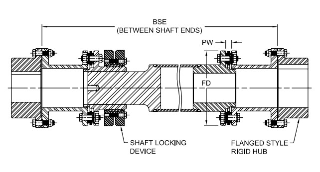 substitute to get a floating shaft design gear coupling. The DILR/DILRA is designed to make use of the hubs already about the customer’s tools. The DILR drop in substitute is going to be produced slightly shorter that the DBFF and shims will likely be made use of for ease of upkeep. The DILRA is adjustable utilizing an SLD (Shaft Locking Device) to produce axial or length changes. Consumers with various pieces of gear with similar length couplings can stock one particular spare spacer which can be employed being a substitute for far more than one particular coupling.
Should the finish consumer needs rigid hubs be provided with all the coupling, a DIR or DIRA Type coupling will probably be advisable and also the BSE (distance Amongst Shaft Ends) should be specified.
Necessary Information and facts:
The finish consumer needs to be ready to supply the following data when contacting Technical Support:
Motor horse power and speed (contain gearbox ratio ¡§C input and output).
Rigid hub sizes (in the event the buyer is using existing F-Style rigid gear coupling hubs).
DBFF or distance among flange faces on the rigid hubs for DILR Sort.
BSE shaft separation is usually specified for DIR Kind.
Shaft sizes for rigid hubs DIR and DIRA Variety couplings.
For maximum bore sizes, check with Gear Coupling Catalog pages F-Style rigid hubs.
DI-6 Style Drop-In Center Industrial Coupling
The DI Type coupling will be the conventional six bolt coupling with two hubs and also a spacer assembly that could be put in or eliminated with out disturbing the gear and hubs and with no removing the disc packs in the spacer assembly. Custom spacer lengths is often specified for exclusive applications. The coupling has two flex planes (one particular at every single disc pack) so it can accommodate parallel misalignment from the angular misalignment in every disc pack. This configuration may even accommodate axial misalignment inside the specified limits.
Characteristics
Designed to meet the  API 610 Common
Help for supplemental API prerequisites offered on request
Unitized disc pack
Infinite daily life if correctly aligned
Torsionally rigid with out any back lash
No have to have for lubrication or servicing
No wearing elements and high resistance to harsh environmental ailments
DI-8 Kind Drop-In Center Industrial Coupling
The DI Variety coupling is the common six bolt coupling with two hubs and also a spacer assembly that can be put in or removed devoid of disturbing the equipment and hubs and without removing the disc packs in the spacer assembly. The coupling has two flex planes (a single at just about every disc pack) so it can accommodate parallel misalignment by the angular misalignment in every disc pack. This configuration will even accommodate axial misalignment inside the specified limits.
Attributes
Made to meet the API 610 Conventional
Help for further API needs accessible on request
Unitized disc pack
Infinite daily life if adequately aligned
Torsionally rigid devoid of any back lash
No will need for lubrication or servicing
No sporting elements and substantial resistance to harsh environmental circumstances
Puller holes typical with this particular design.
SXC-6 Variety Closed Coupled Industrial Coupling
The SXC-6 Kind would be the common six bolt coupling with two hubs, two disc packs and also a spacer. The hubs can both be turned inward to accommodate close coupled applications or a single hub might be turned outward to accommodate more BSE?¡¥s (shaft separation). The coupling has
two flex planes (one at just about every disc pack) so it may accommodate parallel misalignment through the angular misalignment in every disc pack. This configuration may also accommodate axial misalignment in the specified limits.
Options
Unitized disc packs
Infinite daily life if effectively aligned
Torsionally rigid with out any back lash
No require for lubrication or maintenance
No wearing parts and substantial resistance to harsh environmental conditions
Is often combined with SU/SX hub for greater bore capacity
SXCS-6 Kind Closed Coupled Industrial Coupling
The SXCS Sort will be the typical 6 bolt coupling with two hubs, two mounting rings, two disc packs and also a split spacer made for ease of installation and maintenance. Customized spacer lengths could be specified for unique applications. The coupling has two flex planes (a single at every single disc pack) permitting it to accommodate parallel misalignment from the angular misalignment in each disc pack. This configuration may even accommodate axial misalignment inside the specified limits.
Capabilities
Unitized disc pack
Infinite life when effectively sized and aligned
Torsionally rigid without the need of any back lash
No require for lubrication or maintenance
No wearing components and higher resistance to harsh environmental situations
Disc packs may be replaced with no moving tools
For more substantial sizes, refer to SXCST couplings
SXCST-6 Sort Closed Coupled Industrial Coupling
The SXCST Style is usually a conventional 6 bolt  coupling consisting of two hubs, two mounting rings, two disc packs along with a split spacer. Custom spacer lengths is usually specified for distinctive applications. The coupling has two flex planes (one at every disc pack) so it could accommodate parallel misalignment through the angular misalignment in each disc pack. This configuration may also accommodate axial misalignment in the specified limits.
Features
Unitized disc pack
Infinite life when thoroughly sized and aligned
Accommodates angular, axial, and parallel misalignment
Torsionally rigid without having any back lash
No need to have for lubrication or upkeep
No sporting elements and higher resistance to harsh environmental circumstances
Near coupled
Split spacer design enables for ease of maintenance and disc pack elimination or substitute devoid of moving tools.
SU-6 Form Industrial Coupling
The SU Variety coupling is actually a 6 bolt single flex plane coupling which consists of two hubs and one disc pack kit. It’s only suitable for the specified axial and angular misalignment and won’t accommodate parallel misalignment. It is typically mixed with reliable shafts to make floating shaft couplings. See Page D-28 for a picture of an SXFS Variety floating shaft coupling.
Options
Unitized disc pack
Infinite daily life when effectively aligned
Torsionally rigid without any back lash
No need for lubrication or upkeep
No wearing parts and higher resistance to harsh environmental problems
Larger sizes are available upon request
SX-6 Form Industrial Coupling
The SX-6 Kind is often a typical coupling with two hubs, a spacer, and two disc pack kits. The coupling has two flex planes (1 at just about every disc pack) so it could accommodate parallel misalignment through the angular misalignment in each disc pack. This configuration will even accommodate axial misalignment within the specified limits.
Attributes
Unitized disc pack
Infinite life when appropriately sized and aligned
Accommodates angular, axial, and parallel misalignment
Torsionally rigid without having any back lash
No have to have for lubrication or maintenance
No sporting components and large resistance to harsh environmental ailments
Overload Bushings are available
SX-8 Sort Industrial Coupling
The SX-8 Form can be a typical coupling with two hubs, a spacer, and two disc pack kits. The coupling has two flex planes (one at each disc pack) so it might accommodate parallel misalignment through the angular misalignment in every disc pack. This configuration will even accommodate axial misalignment inside of the specified limits.
Options
Unitized disc pack
Infinite daily life if effectively aligned
Accommodates angular, axial, and parallel misalignment
Torsionally rigid with no any back lash
No need 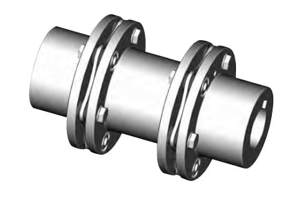 to have for lubrication or upkeep
No sporting parts and high resistance to harsh environmental conditions.
The next information ought to be offered to when putting an purchase to ensure the proper selection of the disc coupling:
Application and type of duty
Kind of driver (engine, motor, turbine, and so forth.)
Speed and horsepower
Type of driven
Shaft sizes and separation
Area limitations for important diameter and length
Style of fit (Interference fit default, clearance fit and shaft locking gadget preparation available on request)
Specific specifications (vertical mounting, drop out center, flange mount, electrically insulated, API-610 as much as 3,800 RPM, shear pins, balancing, etc.)
Angular misalignment, axial misalignment, and rated torque are all related towards the coupling’s capacity to accommodate application torque over any period of time. As illustrated during the following charts, once the application torque increases to 50% in the coupling capability, the means in the coupling to accommodate angular misalignment to is diminished. Exactly the same holds genuine for the ability to accommodate axial misalignment.
Selection Procedure
1. Select the coupling sort.
2. Select the driven machine support element SFA
three. Select the driving machine support issue SFD
Care need to be taken when the 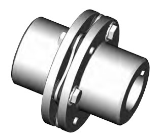 driving machine is other than a common electrical motor or turbine. Some engines will impose more fluctuations around the drive procedure and allowance must be manufactured accordingly. A torsional coupling could be essential for diesel drives.
The next can be a sample application used to illustrate the common system for deciding on a Disc coupling. Any resemblance to any existing company?¡¥s application is neither intentional nor meant to resemble that company?¡¥s actual application.
Sample Application:
A company includes a compressor application making use of a 225 horsepower electric motor running at 1,150 RPM to drive a 3 cylinder multi stage reciprocating air compressor. The electrical motor features a 3-3/8 inch shaft having a 7/8 inch keyway as well as the compressor includes a 92mm shaft that has a 25mm keyway. The shaft separation is roughly 7 inches concerning shaft ends with some capability to modify the motor 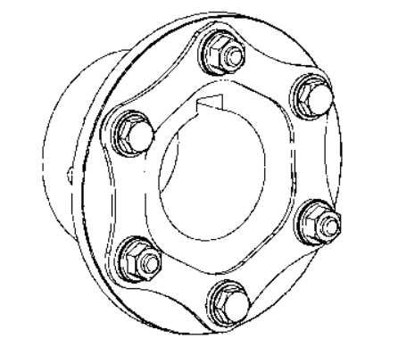 area. The shafts have a parallel misalignment/offset of approximately 1/32 of an inch.
Step 1: The first step will be to ascertain what coupling style is usually to be picked for this application. Because the SU Type coupling only supports
a single flex plane, it could only accommodate angular and axial misalignment, but not parallel misalignment. The next decision might be to search at an SX or DI Sort coupling. The 6 bolt SX Type will accommodate each parallel misalignment and the defined shaft separation. The size will likely be determined through the selection torque plus the shaft diameters.
Phase 2: Up coming, determine the application torque and apply the service element to calculate the variety torque.The formula made use of to calculate torque is as follows:
Application Torque ( in¡§Clb ) = ( HP x 63025 )/RPM
or Nm = ( KW x 9550)/RPM
Plugging during the numbers from the application description:
Application Torque ( in-lbs ) =(HP x 63025)/RPM = (225 x 63025)/1150 = 12,331 in-lbs
Application Torque x Services Factor = Variety Torque
12,331 in-lbs x 3.0 = 36,993 in-lbs
Stage 3: Utilize the SX coupling tables and note that the SX 202-6 is rated at 40,700 in-lbs, over sufficient to manage the selection torque calculated in step two. The SX202-6, even so, will not assistance the 92mm shaft dimension. The subsequent greater size coupling, the SX228-6, will support the 92mm shaft size and also the shaft separation dimension (BSE) is 6.88 inches, pretty close to the application?¡¥s preferred seven inch separation. The SX228-6 is rated at 62,000 in-lbs which may seem to be excessive, nevertheless, the coupling size is necessary to manage the bore size.
Phase four: The SX228-6 coupling is rated to get a maximum unbalanced pace of 3,400 RPM, more than sufficient to assistance the application speed of 1,150 RPM.
Step 5: To find out if your coupling will take care of the parallel misalignment, make use of the trig perform of tan 1?? = offset allowed for one inch = 0.0174
Multiply the 0.0174 x the distance in between disc packs or ??S?¡¥ dimension from your table on page D-13, or 5.50 inches.
The allowable parallel offset is 0.0174 x 5.50 = 0.096 inches. The maximum offset for your application is 1/32 inches (0.031), hence this coupling can accommodate the parallel misalignment.
Note: It truly is generally proposed to endeavor to install the coupling at roughly 20% in the allowable misalignment. For this coupling the installer really should endeavor to reach far better than 0.020 parallel misalignment at the time of set up. This will likely enable to the additional misalignment which will occur because the end result of tools settle and basic tools wear.
Industrial SU Sort
The SU Sort coupling has a single flex plane with two hubs plus a single disc pack. It really is suitable for angular and axial misalignment only. Two SU couplings tend to be mixed having a shaft
to create a floating shaft coupling. The shaft can be hollow for prolonged light excess weight floating shaft couplings.
Industrial SX Form
This is often the regular coupling style that consists of two hubs, a stock length spacer built to meet industry common lengths, and two unitized disc packs. The coupling has two flex planes, 1 at every disc pack, allowing this coupling to accommodate parallel, angular, and axial misalignment with specified limits. The coupling is accessible in 6 and eight bolt styles and bore sizes as much as 13 inches (330mm) over the greatest size. Custom spacer lengths could be produced to meet exclusive shaft separations demanded for particular applications. The SX coupling can be fitted with overload bushings to guard the disc packs in in excess of torque circumstances and might act as an anti-flail device. SX couplings are assembled with the time of set up within the tools in which the coupling is going to be in services.
Industrial DI Kind
The DI Kind coupling has a “Drop-In” spacer assembly that may be assembled at the factory. The coupling consists of two hubs as well as a spacer assembly comprising on the spacer, two unitized disc packs, and two guard rings. The disc packs are bolted for the spacer and guard rings in the factory applying the torque values suggested by Lovejoy for the disc pack bolts. With all the hubs mounted within the shafts, the whole disc pack assembly is usually “Dropped In” location among the 2 hubs. The hubs are piloted to guarantee appropriate centering on the spacer assembly. This piloting serves as an anti-flail function and aids in the coupling’s potential to meet the balance standards mandated by API. This design coupling is developed to meet the stability and anti-flail specifications specified in API-610.
Oversized, or Jumbo, hubs are available for use together with the DI Sort coupling to permit for bigger bore sizes on most DI coupling sizes. This permits to the use of smaller sized DI couplings in applications where a smaller sized dimension coupling can still accommodate the application torque.
Industrial SXC Sort
The SXC Form is the shut coupled variation of the SX Sort coupling. The SXC is much like the SX coupling in the disc packs are connected once the coupling is installed. In the close coupled units, the hubs are turned inward and are mounted within the spacer. Note that together with the hubs within the spacer, the utmost bore permitted inside the hub is going to be decreased. The SXC couplings might be utilized with 1 or each hubs turned outward to permit the coupling to accommodate distinctive shaft separations.
Industrial SXCS and SXCST Styles
The SXCS and SXCST Forms have split spacers and also the disc packs might be serviced or removed without moving the hubs to the shafts and devoid of moving the equipment. The SXCS Form has the bolts that connect the hubs on 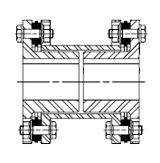 the split spacer installed through the ends on the couplings. The SXCST possess the bolts set up from inside the spacer pointing outward in direction of the hubs.
Additional Types
Our disc packs are produced utilizing higher grade stainless steel
(AISI-301), guaranteeing high power, high endurance to fatigue, and resistance to most environmental 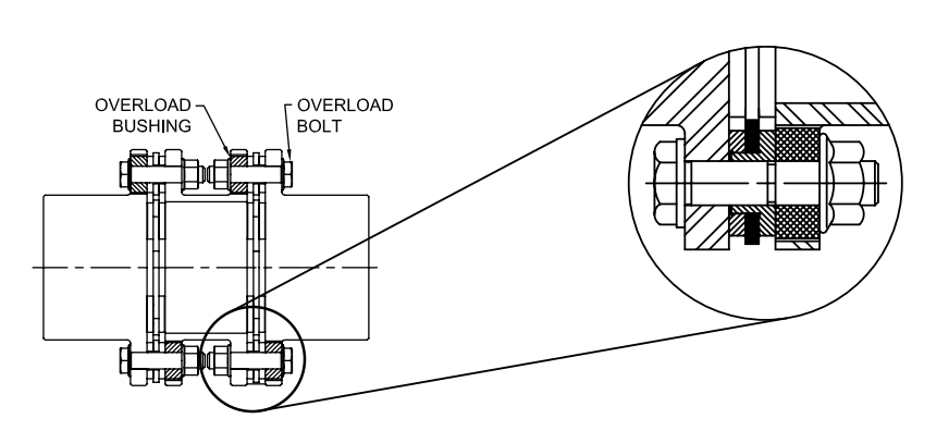 problems.
Disc couplings employ unitized disc packs with each six or 8 bolt designs. The 8 bolt design can transmit higher torque than the 6 bolt design and style, nonetheless, it can be not able to accommodate as a lot angular misalignment.
Couplings could be fitted with overload bushings to guard the disc pack for the duration of momentary torsional overloads.
Couplings are offered in a selection of configurations to match most applications. Additionally, ?¡¥s engineering department can customize a coupling to meet quite a few distinctive necessities such as close coupled, drop-out centers, electrically insulated, vertical mounting, and safety couplings. A notable design provided by is definitely the reduced moment (DI Variety) coupling that meets the anti-flail device requirements mandated in API-610 although offering a reduced weight and brief center of gravity to bearing distance.
The design and manufacture of disc couplings is integrated right into a licensed High quality System according to ISO-9001 to fulfill the higher quality needs of buyers.
Benefits from the Disc Coupling
Eliminates the need for lubrication and coupling maintenance
Coupling might be inspected devoid of disassembly
Condition of disc packs is usually inspected using a strobe light though the machine is operating
Note: It is actually not suggested that couplings be operated with no coupling guards.
Easy to assess gear misalignment
Torsionally rigid with out any backlash
No wearing components
\Resistance to harsh environments
Long lifestyle when thoroughly sized and aligned
High energy density (larger torque for any provided outside diameter)
Supports the API-610 Regular up to three,800 RPM
Unitized disc packs assure repeatability vital for meeting the balance and piloting requirements as mandated by API-610
Offered with Overload Bushings to safeguard the coupling from momentary torque overloads
Prevents the disc pack from currently being plastically deformed
Allows for shorter BSE (shaft separation) mainly because bolts can be turned to face inward
Special orientation of bolts will allow the bolts for being tightened utilizing a torque wrench as an alternative to nuts (Typical is usually to tighten nuts with torque wrench)
The following headings include information on necessary factors for variety and proper utilization of gearbox.
For certain data within the gearbox range,see the pertinent chapters.
1.0 OUTPUT TORQUE
one.one Rated output torque
Mn2 [Nm]
The torque which will be transmitted constantly through the output shaft, with all the gear unit operated under a support issue fs = one.
one.two Essential torque
Mr2 [Nm]
The torque demand based mostly on application requirement. It can be encouraged to become equal to or less than torque Mn2 the gearbox beneath study is rated for.
1.three Calculated torque
Mc2 [Nm]
Computational torque value for being employed when picking the gearbox.
It is actually calculated thinking of the expected torque Mr2 and services component fs, as per the romance here immediately after:Mc2 = Mr2 ?¡è fs ?¨¹ Mn2
2.0 Power
2.1 Rated input energy
Pn1 [kW]
The parameter is often discovered within the gearbox rating charts and represents the KW that will be securely transmitted for the gearbox, based on input pace n1 and support factor fs= one.
2.2 Rated output electrical power
Pn2 [kW]
This worth is definitely the electrical power transmitted at gearbox output. it can be calculated together with the following formulas:
Pn2 = Pn1 ?¡è |?d
Pn2= Mn2*n2/9550
three.0 EFFICIENCY
Efficiency is often a parameter which features a key influence about the sizing of sure applications, and mainly depends on gear pair  designelements. The mesh information table on web page 9 displays dynamic efficiency (n1=1400)and static efficiency values.
Bear in mind that these values are only achieved following the unit has become run in and is with the doing work temperature.
3.1 Dynamic efficiency
[|?d]
The dynamic efficiency could be the relationship of electrical power delivered at output shaft P2 to energy applied at input shaft P1:
|?d =P2/P1
3.2 Static efficiency[|?s]
Efficiency obtained at start-up of the gearbox. Despite the fact that this is often commonly not major aspect for helical gears, it could be instead significant when choosing worm gearmotors operating beneath intermittent duty.
4.0 Services Aspect
The service element (fs ) relies on the operating problems the gearbox is subjected towards the parameters that have to be taken into consideration to pick quite possibly the most sufficient servies element correctly comprise:
1. type of load on the operated machine : A – B – C
two. length of day-to-day operating time: hours/day(?¡Â)
3. start-up frequency: starts/hour (*)
Kind of LOAD: A – uniform,fa?¨¹0.3
B – moderate shocks, fa?¨¹3
C – hefty shocks, fa?¨¹10
fa=Je/Jm
–Je(kgm2) minute of the external inertia lowered with the drive shaft
–Jm(kgm2) minute of inertia of motor
–If fa>10 please get in touch with our Technical Service
A -Screw feeders for light components, fans, assembly lines, conveyor belts for light resources, compact mixers, lifts, cleansing machines, fillers, manage machines.
B -Winding devices, woodworking machine feeders, goods lifts, balancers,threading machines, medium mixers, conveyor belts for hefty materials,winches, sliding doors, fertilizer scrapers, packing machines, concrete mixers, crane mechanisms, milling cutters, folding machines, gear pumps.
C -Mixers for heavy components, shears, presses, centrifuges, rotating supports, winches and lifts for heavy materials, grinding lathes, stone mills, bucket elevators, drilling machines, hammer mills, cam presses, folding machines, turntables, tumbling barrels, vibrators, shredders.
JDLB series higher precision worm gear is definitely an best substitute for precision planetary gearbox,the tools producer can considerably minimize the price of employing precision planetary gearbox .Hollow output with shrink disc, high precision , for uncomplicated integration.Output with keyway, handy set up, simple integration.Strong shaft output (single, double ), large stiffness, common resolution.The designer’s perfect solution would be to rotate 90 degrees to install the servo motor drive systems.Worm shaft in series is usually driven by one particular motor to accomplish synchronous output of a number of worm wheels. It has been applied in automatic polishing mobile phone shell as well as other equipments.
Optimized contact pattern
Superior processing technology and precision assembly to be sure the right meshing from the tooth and reduce make contact with tension of the tooth surface
Particular worm wheel bronze alloy helps make the teeth have high strength and superior dress in resistance.
Having a substantial ratio of tooth surface get hold of, worm wheel isn’t uncomplicated to wear , it may possibly retain the locked backlash .
Optimized adjustment construction
Rapidly setting backlash
Higher stiffness and precision
Patent structure
Worm shaft making use of Taper roller bearings
Set up two taper roller bearings with which have longer support lives.
Eliminates worm shaft alignment issues
Bearing pre-tight set up, with increased help stiffness
Servicing free
Higher functionality synthetic lubricant
Closed framework, no have to have to replace lubricant oil.
Quickly set up servo motor
Substantial stiffness and reduced inertia coupling for servo motor
Various flanges can be matched together with the servo motor
Put in two taper roller bearings with which have longer service lives.
Eliminates worm shaft alignment difficulties
Bearing pre-tight installation, with greater assistance stiffness
Output torsional backlash accessible in 2 ranges:
Ultra precision: 1 arc minute for that most demanding applications
Precision: 2 to 4 arc minutes an excellent  compromise value and good quality
Housing with gravity casting
Higher power Aluminum Alloy casting and heat treatment
Superior rigidity and very low bodyweight
Gorgeous shape and Fantastic weather resisting property
Machine Kind
one.Conveyors
Typical lndustnes :
Sand & Gravel, Animal Feeds,Water Treatment,Agriculture,Quarrying,Baggage Handing,Baggage Handing,Port Authorities,Post & Parcel,Grain Dryers
Application Example :
1.Head drum drive for stcreen feeder.
two.Main drive on are inclined basalt conveyor.
3.Ship loading elevator.
4.Main drive to screw conveyer.
5.Overland buck conveyor drives.
6.Main drive 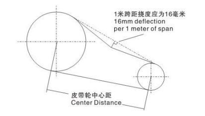 for transporting animal floods.
7.Airport baggage handling conveyors
2. Mixers & Mills
Standard lndustnes : Animal,Feeds,Food,Industry,Agriculture,Petrochemical,Paint,Process,Industries,Aerators
Application Example :
one.Biscuit dough mixer
two.Main drive to animal feel mill
3.Main drive for Asphalt agitator
4.Paddle drive on animal feed processing piant.
3. Other Applications
Common lndustnes:
Cranes & Hoists,Winches,Tanning & Processing ,Textile Machinery,Laundry Machines,Machine tools,shears,etc.
Application Example:
one.Reversing duty on an industrial washing machine.
two.Container liftlng equipment.
3.Driven by an air motor on an under water winch system.
4.Wind turbine drive-used as speed increasing drive to generate electricity.
Process of Belt Tensioning
one. Calculate the deflection distance in mm on a basis of 16mm per meter of span. Center distance(m) x 16=Defection(mm).
two. Use a spring balance and rule measure the force on the belt, in case the value falls inside of the values provided, the drive ought to be satisfactory. Othewise, utilize the Torque arm’s turnbuckle change the tension of the belt. (Note, the force course and the belt must be a appropriate angle).
SMR Gearbox Installation
Satisfactory effectiveness will depend on proper set up. lubrication and servicing. therefore it’s important the guidelines while in the installation and servicing leaflet. supplied with each and every gearbox. are followed thoroughly. a number of the vital elements of belt and torque-arm set up are listed below.
one. Install pulley on gearbox input shaft as shut on the reducer possible, and mount reducer on driven shaft as close to bearing as sensible. failure to carry out this may result in excess loads while in the input shaft bearings and output bearings and could bring about their premature failure.
two. Install motor and wedge belt drive using the belt pull at around 90° on the center line involving driven and input shafts. this can permit tensioning on the wedge belt drive together with the torque arm which ought to ideally be in stress. if output hub runs anti-clockwise. torque arm needs to be positioned the ideal.
3. lnstall torque-arm fulcrum on a rigid support so that the torque-arm are going to be at somewhere around ideal angles for the center line with the driven shaft plus the torque arm case bolt. make sure there is sufficient consider up from the turnbuckle for belt stress adjustment.
Preserve close.
Bell drive may be situated in any convenient postion. if the 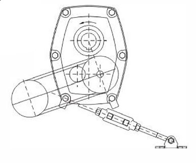 torque arm is always to be utilised to tighten the belts, the drive need to be at about tight angle towards the line concerning the input and output shafts.
Bell drive can be located on the appropriate if desired.
If output hub rotates clock-wise. place belt drive and torque arm in opposite direction to that proven during the illustration.
Torque arm and belt consider up.
Torque arm may very well be mounted to the right if preferred.
how you can order the SMR gear box
Gearbox Coding
Gearbox coding
Very first 3 letters: SMR
Fourth letter, unit dimension: BCD EFG HJ
Fifth and sixth digits, ratio code: 05 13 20
Seventh digit. indicates assembly: O shaft mounted velocity reducer 2 flange mount
Eighth digit: signifies output hub bore necessary: 1 conventional metric bore. 2 alternative metric bore.
Illustration
Size e unit twenty:one nominal gear ratio, shaft mounted with typical metric hub bore (55mm): SMR-E2001
It backstop are necessary, these must be purchase individually. and must specify the output hub rotation. E.g.: SMR-E2001 complete with backstop. during the input shaft side, the output hub’s rotation is in clockwise.
optional Extras
Backstops 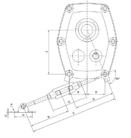
A backstop could be integrated on applications in which it’s important to reduce reversal of rotation. it’s immediately put in within the reducer, by just getting rid of a cover plate
Note: For ratio 5: one gear box, backstop tend not to recommended.
Flange mounting
SMR situation design and style is such the reducer can be bolted direct to supporting framework. this flange mounting utilization of the reducer may well permit designers to omit a bearing or pillow block, nonetheless it does. of course. reduce the simple belt adjustment feature characteristic of shaft mount.
Note: Common SMR gearbox do not drill mount screws. when client want these sorts mount, please specify while in the buy.
Shaft Mount Reducer are metric in style all through and have energy ratings to AGMA conventional. Shaft Mount Reducers supply an extremely hassle-free system of minimizing speed, because it is mounted directly over the driven shaft in lieu of requiring foundations of its own. It eliminates the usage of a single, and sometimes two, versatile couplings and external belt take-up arrangements, A torque-arm anchors the reducer and provides swift, straightforward adjustment of your Wedge Belts by means of its turnbuckle.
Shaft Mount Reducers are produced in eight gear case sizes, nominal gear ratios are 5:1, 13: 1 and twenty: one, An exceptionally broad preference of last driven speeds might be established by the utilization of an proper input Wedge Belt Drive.
The units will commonly be oil lubricated, nevertheless they are equally ideal for prolonged life synthetic lubricants.
Establish the output pace of the gear units, multiply the absorbed electrical power (or Motor electrical power if absorbed power nit acknowledged) through the service factor picked in phase 1.
Note: Gear units are momentarily capable of transmitting twice (2X) the rated capacity on get started or during operation.
Unit choice
The preference of single or double reduction gearbox will probably be established from the output velocity needed . The usual working speeds for every of the gearboxes can be observed within the electrical power rating and belt drive tables.
Note : When use 5:1 Gear Units, the Back quit usually do not encouraged.
selection of associated belt drive for 1440 rpm electric motors
1.0utput Velocity
Refer on the Drive Choice Tables and below the appropr-late gearbox dimension and ratio read down the column headed ‘Output Speed’until an Output Pace equal or close to to that necessary is found. The advised gearbox ratio is provided during the first column
two.Pulley Diameters
Read through across through the chosen output velocity to acquire both driving and drives pulley pitch diameters, groove part as well as ideal quantity of belts.
Note: in lots of situations 1 belt is recommended, remaining adequate for power transmission functions
3.Center Distance
Belt length and center distance could be found by referring to your acceptable pages with the “Wedge Belt Drives” catalogue.
Choice of related belt for driving speeds aside from 1440 rpm
1.Gearbox input Shaft Pace
Multiply the gearbox output speed from the Exact GEAR RATIO to obtain the gearbox input shaft speed.
two.Assortment of’V’ Drive
The correct belt drive can now be selected referring to the’wedgr Bely Drives’ catalogue.
1.Output Hubs
Regular or alternate hubs with metric bores are available to suit inter nationwide shaft diameters.
2. Precision Top 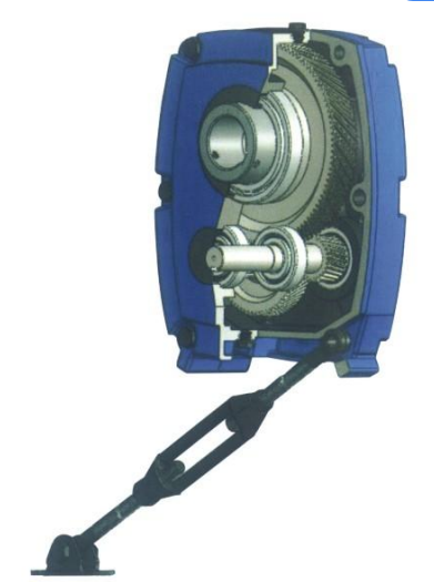 quality Gearing
Computer system Built Helical Gear. Sturdy Alloy Materials for Substantial Load Capacity, Situation Carburized for long lifestyle, Ground Profile (some intermediate pinions are shaved), Crown tooth Profile, In Conformance with ISO 1328-1997, 98% Efficiency for per Stage, Smooth Quiet Operation with Teeth in Mesh.
3.Maximum Capacity Housing Design and style
Shut Grain Cast Iron Construction, Excellent Vibration Dampening & shock Resistance features, Precision Bored and Dowelled to Ensu?oe Accurate In¨°?line Assembly.
4.Strong Alloy Steel Shafts
Strong Alloy Steel, Hardened, Ground on journals, Gear Seatings and Extensions, for Maximum Load and Maximum Torsional Loads, Generous Sizes Shaft Keys for Shock Loading and Conform to ISO Standards.
5.Additional Case Lugs(Except H and J Gear Situation)
Eliminates the Need for Critical Tightening of Torque arm Bolts, Controls Position of Typical Torque Arm Mounting within Recommended limits.
6.Backstops
Option Parts, Anti-run Back Device, Are available on all 13:1 and 20:1 Ratio units and do not recommend for 5:1 Units.
7.Bearing and Oil seals
Bearing are Adequately Proportioned and Conform to ISO dimension plan, Readily Out there World-wide, Oil seals are Double Lipped Garter Spring Type, Ensuring Effective Oil Sealing.
8.Rubberised End Caps
Self Sealing Intermediate Cover Plates, to Standard ISO Housing Dimensions.
9. Torque Arm Assembly
For Easy Adjustment of the Belt
Standard Description
Equiped that has a reversible motor, a bidirectional gear pump, double P.O. checke valves, relief valves and a tank, this power unit can drive a double acting cylinder to extend and retract without a directional solenoid valve. It really is normally used in recre-ational cars, pleasure boats and moveable phases, and so on.
Particular Notes
one. 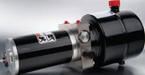 This power unit is of S3 duty cycle, i.e., non-continuous operation, thirty seconds on and 270 seconds off.
2. Clean each of the hydraulic components concerned prior to set up of the electrical power unit.
three. Viscosity from the hydraulic oil shoud be 15~46 cst, which should also be clean and free of impurities. N46 hydraulic oil is recommended.
4. The electrical power unit proven is built to be mounted horizontally.
5. Oil changing is needed after the initial 100 operation hours, afterwards when every 3000 hrs.
6. Check the oil level in the tank right after the initial running from the energy unit.
Standard Description
Equiped that has a reversible motor, a bidirectional gear pump, double P.O. checke valves, relief valves and a tank, this power unit can drive a double acting cylinder to extend and retract without a directional solenoid valve. It really is normally used in recre-ational cars, pleasure boats and moveable phases, and so on.
Particular Notes
one. This power unit is of S3 duty cycle, i.e., non-continuous operation, thirty seconds on and 270 seconds off.
2. Clean each of the hydraulic components concerned prior to set up of the electrical power unit.
three. Viscosity from the hydraulic oil shoud be 15~46 cst, which should also be clean and free of impurities. N46 hydraulic oil is recommended.
4. The electrical power unit proven is built to be mounted horizontally.
5. Oil changing is needed after the initial 100 operation hours, afterwards when every 3000 hrs.
6. Check the oil level in the tank right after the initial running from the energy unit.
Basic Description
Equiped having a reversible motor, a bidirectional gear pump, double P.O. checke valves, relief valves and also a tank, this power unit can drive a double acting cylinder to extend and retract without a directional solenoid valve. It is ordinarily used in recre-ational automobiles, pleasure boats and transportable stages, and so on.
Specific Notes
one. This electrical power unit is of S3 duty cycle, i.e., non-continuous operation, 30 seconds on and 270 seconds off.
2. Clean each of the hydraulic elements concerned ahead of installation of the electrical power unit.
3. Viscosity with the hydraulic oil shoud be 15~46 cst, which must also be clean and free of charge of impurities. N46 hydraulic oil is proposed.
4. The electrical power unit shown is made to be mounted horizontally.
5. Oil altering is required after the original 100 operation hrs, afterwards as soon as just about every 3000 hours.
6. Check the oil level within the tank immediately after the initial working on the energy unit.
Power UNITS FOR LIFT TABLE 1
Common Description
This electrical power unit is created exclusively for your tiny lift table,Consisting of large stress gear pump, AC motor, multi-functional manifold, valves, tank, and so forth. This energy unit has been broadly utilised inside the marketplace of logistic units including minifork lift, scissors lift and ariel functioning platforms. The lower-ing motion is managed from the solenoid valve using the speed managed by the adjustable needle valve.
Power UNITS FOR LIFT TABLE two
General Description
This energy unit is developed exclusively for that medium lift table, Consisting of hugely effecient gear pump, AC motor, multifunctional manifold, valves, tank, ect. The reducing movement is actived through the solenoid valve plus the speed managed by the adjustable needle valve. When the lift rises to a high positoin, but the energy provide is cut, the lowering movement is controlled from the guide override function.
Energy UNITS FOR LIFT TABLE three
Common Description
This power unit is designed solely for that substantial lift table, Consisting of remarkably effecient gear pump, AC motor, multi-functional manifold, valves, tank, ect. The decreasing motion is actived from the solenoid valve along with the speed controlled by a stress compensated movement management valve.
Electrical power UNITS FOR LIFT TABLE four
General Description
This energy unit is developed exclusively to the substantial lift table, Consisting of highly effecient gear pump, AC motor, multi-functional manifold, valves, tank, ect. The reducing motion is actived by the solenoid valve and also the pace managed from the adjustable needle valve. When the lift rises to a substantial positoin, but the power supply is minimize, the reducing motion is managed from the manual  override perform.
Distinctive Notes
one. This power unit is of S3 duty cycle, which can only perform intermittently and repeatedly, i.e. one minute on and 9 minutes off.
2. Clean all of the hydraulic components concerned prior to set up of the electrical power unit.
3. Viscosity of the oil shoud be 15~46 cst,which ought to also be clean and absolutely free of impurities.N46 hydraulic oil is encouraged.
4. Oil altering is needed following the preliminary one hundred operation hours,afterwards the moment every 3000 hours.
5. The power unit proven is intended to be mounted vertically.
Power UNITS FOR DOCK LEVELER one
Basic Description
This Dock leveler power unit simply just raised the ramp once the motor is activated, when the ramp has reached full extension the sequence shifts to lengthen the lip. The ramp and lip are lowered by separate solenoid valves though the descent. Each the ramp and lip f of each functions are managed by a needle valve. The needle valves are adjustable to attain the wanted descent velocity of each perform.
Electrical power UNITS FOR DOCK LEVELER two
Basic Description
This Dock leveler electrical power unit just raised the ramp once the motor is activated, when the ramp has reached total extension the sequence shifts to extend the lip. The ramp and lip are lowered by separate solenoid valves when the descent. Both the ramp and lip f of each functions are controlled by a needle valve. The needle valves are adjustable to realize the preferred descent velocity of every perform.
Electrical power UNITS FOR DOCK LEVELER three
General Description
This 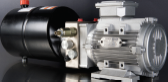 Dock leveler power unit just raised the ramp once the motor is activated, when the ramp has reached complete extension the sequence shifts to extend the lip. The ramp and lip are lowered by separate solenoid valves even though the descent. The two the ramp and lip f of every functions are controlled by a needle valve. The needle valves are adjustable to attain the wanted descent velocity of every function. The 2nd relief valve guarantees the principle platform to become floating beneath load once the dock leveler is being used for loading and unloading the products, thus protecting the dock leveler effectively.
Common Description
This power unit characteristics a long lasting magnet motor having a power up gravity down circuit. Activate the commence solenoid to start the motor to lift the machine. The lowing movement is activated by the solenoid valve with all the lowering speed managed through the stress compensated movement management valve. Goods of this series is often extensively utilized in the business of logistic gadgets such as fork lift, mini lift table, etc.
Special Notes
1. This power unit is  of S3 duty cycle, i.e.,non-continuous operation, thirty seconds on and 270 seconds off.
2. Clean every one of the hydraulic parts concerned ahead of set up of the power unit.
3. Viscosity with the hydraulic oil shoud be 15~46 cst, which really should also be clean and no cost of impurities. N46 hydraulic oil is advised.
four. This energy unit is built to be mounted vertically.
5. Check the oil degree during the tank after the 1st star on the energy unit.
6. Oil modifying is required following the initial 100 operation hrs,afterwards as soon as every 3000 hours.
7. More pump sizes and tank sizes are avaiable upon request.
Material Handling Power UNIT 1
Basic Description
This power unit is developed for the fork lift market, consisting of really productive gear pump, DC motor, manual raise and decrease valve, tank, ect. The up and down movement are controlled from the lever in the manual release valve, and that is outfitted with an electrical switch to activate the motor. The lowing speed is managed through the strain compensated flow management valve.
Exclusive Notes
1. The duty of this electrical power unit is S3, i.e. thirty seconds on and 270 senconds off.
two. Clean all of the hydraulic parts concerned just before installation of the power unit.
three. Viscosity from the hydraulic oil shoud be 15~46 cst, which should also be clean and no cost of impurities, N46 hydraulic oil is recommended .
4. Oil changing is needed immediately after the original 100 operation hours, afterwards after each 3000 hrs.
5. The electrical power unit shown is made to be mounted horizontally.
Materials Managing Electrical power UNIT 2
Basic Description
This energy unit features energy up gravity down circuit. Activate the start solenoid to start the motor to lift the machine. The lowing motion is activated by the solenoid valve with all the lowering pace managed from the stress compensated flow management valve. Merchandise of this series may be extensively used in  the field of logistic products such as fork lift, mini lift table, and so on.
Exclusive Notes
1. The duty of this electrical power unit is S3,i.e.,30 seconds on and 270 senconds off.
two. Clean each of the hydraulic elements concerned before mounting the energy unit.
3. Viscosity of the hydraulic oil shoud be 15~46 cst,which ought to also be clean and free of impurities, N46 hydraulic oil is encouraged .
four. Oil transforming is needed just after the preliminary one hundred operation hrs,afterwards as soon as each and every 3000 hours.
five. The electrical power unit need to be mounted horizontally.
Basic Description
Consisting of the strain balanced gear pump, DC motor, multi-functional manifold, valves, tank, ect., this energy unit is intended to operate materials managing gear. The decreasing movement is achived by the solenoid valve together with the decreasing speed managed by an adjustable needle valve. The left and right functions are outfitted with a dual pilot operated examine valve and cross-over relief valves.
Remark: Please talk to our product sales engineer to the diverse pump displacement, motor electrical power or tank capability.
Special Notes
one. This electrical power unit is of S3 duty cycle, i.e.,non-continuous operation,30 seconds on and 270 seconds off.
2. Clean all of the hydraulic elements concerned in advance of set up of the power unit.
3. Viscosity on the hydraulic oil shoud be 15~46 cst, which 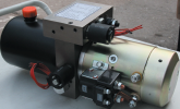 need to also be clean and free of impurities.N46 hydraulic oil is recommended.
four. This electrical power unit ought to be mounted horizontal.
5. Check the oil level from the tank immediately after the primary start out with the energy unit.
six. Oil shifting is required soon after the first a hundred operation hrs, afterwards after every single 3000 hours.
DUMP TRAILER Electrical power UNIT-DOUBLE ACTING
General Description
This energy unit features a power up energy down circuit with load holding on each A & B ports. A stress compensatred movement handle might be additional to circuit to manage the decent velocity from the cylinder.
Exclusive Notes
1. This power unit is of S3 duty cycle, i.e., non-continuous operation, 30 seconds on and 270 seconds off.
2. Clean each of the hydraulic parts concerned before installation of the energy unit.
three. Viscosity in the hydraulic oil shoud be 15~46 cst, which should also be clean and free of charge of impurities. N46 hydraulic oil is encouraged.
4. The energy unit needs to be mounted horizontally.
5. Check the oil degree during the tank just after the original running with the energy unit.
six. Oil altering is needed soon after the original a hundred operation hrs, afterwards the moment each 3000 hrs.
DUMP TRAILER Energy UNIT- SINGLE ACTING
General Description
This electrical power unit includes a power up gravity down circuit. Start out the motor to lengthen the cylinder and activate the solenoid valve to retract the circuit. Manual override to solenoid valve could be presented if required. Also a strain compen sated movement control could be additional to your circuit to regulate the descent velocity with the cylinder.
Remark: Please check with our revenue engineer for that distinctive pump displacement, motor electrical power or tank capacity.
Special Notes
one. This power unit is of S3 duty cycle, i.e., non-continuous operation,  30 seconds on and 270 seconds off.
2. Clean all of the hydraulic elements concerned in advance of installation of the energy unit.
3. Viscosity in the hydraulic oil shoud be 15~46 cst,which should really also be clean and absolutely free of impurities.N46 hydraulic oil is advised.
4. The power unit needs to be mounted horizontally.
five. Check the oil degree inside the tank after the preliminary running from the energy unit.
six. Oil transforming is required soon after the original a hundred operation hours, afterwards as soon as each 3000 hours.
Basic Description
Outfitted with the zero leak bidirectional checking sole-noid valves, this electrical power unit is intended for the operation of two independent circuits. Which are respectively to the major and subordinate platforms from the double scissors lift. Two cut-off  valves are made use of for lowering the machine manually in situation of electrical power loss. If extra independent circuits are needed for your application please make contact with us for availability.
Remark: 1. Please talk to our sales engineer to the diverse pump displacement, motor energy or tank capability.
2. CSA or UL certified motors can be found upon request.
Exclusive Notes
1. The AC motor is of S3 duty cycle, which can only operate intermittently and repeatedly, i.e., 1minute on and 9 minutes off.
two. Clean all of the hydraulic elements concerned ahead of set up of the electrical power unit.
3. Viscosity in the oil shoud be 15~46 cst,as well as the oil must be clean and cost-free of impurities,N46 hydraulic oil is recommended.
4. The power unit should really be mounted vertically.
5. Check the oil level inside the tank right after the first operating of your power unit.
six. Oil shifting is required right after the original 100 operation hours,afterwards after every single 3000 hours.
Introduction
A mindful assessment of your conditions surrounding a conveyor is critical for correct conveyor chain selection. This section discusses the essential considerations needed for productive conveyor chain selection. Roller Chains are sometimes made use of for light to reasonable duty materials handling applications. Environmental situations may possibly demand the use of specific resources, platings coatings, lubricants or even the means to operate without the need of more external lubrication.
Fundamental Data Necessary For Chain Selection
? Type of chain conveyor (unit or bulk) which include the process of conveyance (attachments, buckets, via rods and so forth).
? Conveyor layout together with sprocket locations, inclines (if any) and the variety of chain strands (N) to get employed.
? Amount of material (M in lbs/ft or kN/m) and type of material to become conveyed.
? Estimated fat of conveyor elements (W in lbs/ft or kN/m) together with chain, slats or attachments (if any).
? Linear chain pace (S in ft/min or m/min).
? Environment during which the chain will operate such as temperature, corrosion circumstance, lubrication affliction and so forth.
Phase 1: Estimate Chain Stress
Use the formula below to estimate the conveyor Pull (Pest) and then the chain tension (Test). Pest = (M + W) x f x SF and
Test = Pest / N
f = Coefficient of Friction
SF = Velocity Factor
Step 2: Create a Tentative Chain Assortment
Working with the Test value, make a tentative selection by deciding on a chain
whose rated functioning load higher than the calculated Check worth.These values are ideal for conveyor service and therefore are diff erent from people shown in tables in the front of your catalog that are related to slow velocity drive chain usage.
On top of that to suffi cient load carrying capacity normally these chains has to be of a certain pitch to accommodate a sought after attachment spacing. For instance if slats are to be bolted to an attachment just about every 1.5 inches, the pitch of the chain selected ought to divide into one.5?¡À. Therefore 1 could use a forty chain (1/2?¡À pitch) using the attachments every single 3rd, a 60 chain (3/4?¡À pitch) using the attachments every single 2nd, a 120 chain (1-1/2?¡À pitch) with the attachments each pitch or a C2060H chain (1-1/2?¡À pitch) with the attachments just about every pitch.
Step 3: Finalize Variety – Calculate Real Conveyor Pull
Soon after producing a tentative assortment we need to verify it by calculating
the real chain stress (T). To try and do this we should fi rst determine the actual conveyor pull (P). From your layouts shown within the suitable side of this webpage opt for the suitable formula and calculate the total conveyor pull. Note that some conveyors might be a mixture of horizontal, inclined and vertical . . . in that case determine the conveyor Pull at each area and add them collectively.
Step 4: Calculate Maximum Chain Stress
The maximum Chain Stress (T) equals the Conveyor Pull (P) as calculated in Stage 3 divided by the variety of strands carrying the load (N), occasions the Speed Element (SF) proven in Table 2, the Multi-Strand Aspect (MSF) shown in Table three as well as the Temperature Component (TF) shown in Table 4.
T = (P / N) x MSF x SF x TF
Phase 5: Check the ?¡ãRated Working Load?¡À on the Chosen Chain
The ?¡ãRated Operating Load?¡À from the chosen chain need to be better than the Greatest Chain Stress (T) calculated in Phase 4 above. These values are proper for 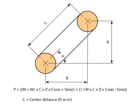 conveyor support and therefore are diff erent from those shown in tables at the front with the catalog which are associated with slow velocity drive chain usage.
Step six: Examine the ?¡ãAllowable Roller Load?¡À on the Chosen Chain
For chains that roll about the chain rollers or on top rated roller attachments it really is essential to examine the Allowable Roller Load?¡À.
Note: the Roller load is established by:
Roller Load = Wr / Nr
Wr = The total weight carried from the rollers
Nr = The amount of rollers supporting the bodyweight.
Leaf Chains are manufactured for high load, slow velocity stress linkage applications. Typically they can be  specifi ed for reciprocating motion lifting gadgets such as fork lifts or cranes. These chains are typically supplied to a specifi c length and are connected to a clevis block at just about every end. The clevis may well accommodate male ends (within or often called “articulating” back links) or female ends (outside or the hyperlinks within the pin link) as essential (see illustration under)
Leaf chains can be found in three series; AL (light duty), BL (heavy duty), or LL (European common). For new choices we advocate the BL series in preference to the AL series because the latter has been discontinued as a acknowledged ASME/ANSI typical series chain. BL series chains are made in accordance with the ASME/ANSI B29.8 American Leaf Chain Standard. LL series chains are produced in accordance with the ISO 606 global leaf chain typical.
A chain with an even amount of pitches often includes a a single male and one particular female end. It is extra frequent to get the chain possess an odd variety of pitches by which case the the two ends will likely be either male (most common) or female (less com-mon). When ordering lengths with an odd quantity of pitches male ends are supplied unless otherwise mentioned. Clevis pins, normally with cotters at each finish, are applied to connect male chain ends to female clevis blocks. Chains with female ends are often (but not generally) connected on the clevis block which has a cottered sort connecting link. The connecting link is definitely the female end component in this instance.
Leaf Chain Selection
Make use of the following formula to confirm the collection of leaf chain:
Minimal Greatest Strength > T x DF x SF
T: Calculated Highest Chain Stress
DF: Duty Component
SF: Service Component
Note that the greatest allowable chain speed for leaf chains is 100ft per minute.
Basic Information
We offer one of several most intensive lines of specialty Servicing No cost roller chain items out there to fi t a wide array of unique application requires. Designers can choose the series that very best fi ts the unique requirements with the application. These chains ought to be specifi ed only when situations prohibit the use of lubricating oil considering that, usually, a properly lubricated standard chain will off er longer existence compared which has a maintenance free chain. In some applications however lubrication isn?¡¥t feasible and so the usage of a self lubricated or sealed roller chain is important.
General Properties of Maintenance Totally free Roller Chain Merchandise
Sintered Bushed (SL-Series) Chains
Oil impregnated powdered metal sintered bushings release oil on the chain joint due to the friction created concerning 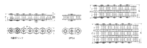 the pin and bushing since the chain articulates more than the sprocket teeth. These chains are rollerless and as a result use thick sectioned powdered metal bushings which may hold a substantial volume of oil.
PT Form Roller Chains
Oil impregnated powdered metal sintered bushings release oil to your chain joint as a result of friction formulated amongst the pin and bushing since the chain articulates in excess of the sprocket teeth. These chains possess rollers to smooth the action over sprocket teeth. Roller website link plates are a single size thicker to improve power. Side plates and pins have exclusive coatings to prevent rust.
C-Type Roller Chains
Very same as above except that the side plates are all conventional thickness. The power of the CS Style chains is under the PT Type but greater compared to the SL style. Attachments with common dimen-sions can be utilized for this series and thus they’re typically used on tiny material dealing with conveyors.
P-Ring Chains
Specifi ed on smaller sized pitch roller chains O-Ring chains utilize a rubber seal to maintain lubricating grease in though avoiding the penetration of dirt and other contaminants in to the pin/bush-ing bearing area.
Seal Guard Roller Chains
Specifi ed on bigger pitch roller chains Seal Guard chains make use of a stainless steel seal to help keep lubricating grease in even though avoiding the penetration of filth along with other contaminants in to the pin/bushing bearing location.
Kind 304 Stainless
All components are produced from AISI Form 304 (18-8) austenitic stainless steel. This materials off ers excellent chemical and temperature resistance within a wide array of various applications. Because Form 304 stainless steel are not able to be heat treated the mechanical power and dress in performance is inferior to regular carbon steel chains.
Variety 316 Stainless
All elements are created from AISI Sort 316 Molybdenum-bearing stainless steel. The molybdenum offers the alloy far better general corrosion resistance in contrast with Variety 304 stainless steel notably larger resistance to pitting and strain corrosion cracking within the presence of chlorides. Mechanical power and dress in functionality are similar to Type 304 stainless steel chain.
600 Series Stainless
Pins, bushings and rollers are produced from 17-4PH stainless steels which could be age hardened for improved resistance to wear elongation. The corrosion resistance of this series is similar (although somewhat inferior) to Type 304 stainless steel. The operating temperature range of this material on the other hand is additionally not as wide as Kind 304 stainless steel.
Mega Chain:
All elements are produced from AISI Sort 304 (18-8) austenitic stainless steel. Offered in two versions (Mega Chain and Mega Chain II) which use diff erent physical confi gurations to obtain extra strength that is comparable to that of carbon steel chains. The functioning loads of those chains are superior to that of conventional 304 stainless steel chains on account of a better pin/bushing bearing regions. In addition both versions possess a distinctive labyrinth type seal design and style that aids protect against the penetration of abrasive foreign components to the internal wearing components.
Common Details
We off er many different corrosion and/or temperature resistant roller chain items to suit the distinct requires of almost any application. These range from plated or coated carbon steels to a variety of diff erent stainless steel types that may be chosen primarily based within the preferred blend of wear resistance, power, corrosion resistance and resistance to extremes in working temperatures.
Nickel Plating
Suitable for mild corrosive circumstances this kind of as outdoor services. Typically utilised for decorative purposes. Chain elements  are plated just before assembly for uniform coverage of inner elements.
Form 304 Stainless
Our conventional stainless steel solution off ers great resistance to corrosion and operates effectively in excess of a wide variety of temperatures. This material is slightly magnetic because of the get the job done hardening in the parts throughout the manufacturing processes.
Form 316 Stainless
This materials possess better corrosion and temperature resistance in contrast with Kind 304SS. It truly is generally utilized in the foods processing market because of its resistance to worry corrosion cracking during the presence of chlorides this kind of as are located in liquid smoke. The magnetic permeability of this material is extremely very low and it is usually deemed nonmagnetic nonetheless it truly is not regarded as to become prspark oof.
600 Series Stainless
Pins, bushings and rollers are produced from 17-4PH stainless steels which could be hardened for improved resistance to put on elongation. The corrosion resistance of this chain is much like
Sort 304SS. The working temperature selection of this materials nonetheless is not really as terrific as Variety 304SS.
Mega Chain:
A higher power 304 stainless steel chain. Offered in two versions which use diff erent mechanical confi gurations to get more power. Each versions off er larger operating loads because of a better pin/bushing bearing place along with a exceptional labyrinth type seal that aids stop the penetration of abrasive foreign resources on the inner sporting elements.
Double Pitch roller chains are created in accordance with the ASME/ANSI B29.3 (Transmission Series) and B29.four (Conveyor Series) American roller chain requirements. Generally these chains are comparable to ASME/ANSI conventional goods except that the pitch is double. They can be accessible in Transmission Series, Conveyor Series with Conventional (small) Rollers and Conveyor Series with Large (oversized) Rollers.
Transmission Series
This series is often utilized on drives with slow to reasonable speeds, lower chain loads and prolonged center distances. Side plates have a fi gure ?¡ã8?¡À contour. The chain amount is obtained by incorporating 2000 to the ASME/ANSI chain number and the prefi x letter ?¡ãA?¡À. Note that some providers usually do not use a prefi x letter for this series so the chains may well be represented as A2040, A2050 and so on. or 2040, 2050 etc.
Conveyor Series with Conventional (small) Rollers
This series is often made use of on light to moderate load material handling conveyors with or without the need of attachment links. The side plate contour is straight for enhanced sliding properties. Pitch sizes of 1-1/2?¡À and greater have ?¡ãHeavy?¡À series link plates (i.e. hyperlink ![]() plates on the next greater chain size. The chain amount is uncovered by including 2000 to your ASME/ANSI chain number and the prefi x letter ?¡ãC?¡À. Chains using the ?¡ãheavy?¡À type side plates use a suffi x letter ?¡ãH?¡À.
plates on the next greater chain size. The chain amount is uncovered by including 2000 to your ASME/ANSI chain number and the prefi x letter ?¡ãC?¡À. Chains using the ?¡ãheavy?¡À type side plates use a suffi x letter ?¡ãH?¡À.
Conveyor Series with Huge (oversized) Rollers
These chains possess big rollers to ensure that the chain rolls on a conveyor track lowering friction. Chain numbers are located during the exact same way as noted above except the last digit over the chain amount is modified from ?¡ã0?¡À to ?¡ã2?¡À which denotes the big roller.
Sprockets
Generally sprockets really should be generated specially for these chains in accordance towards the ASME/ANSI B29.3 and B29.4 standards nevertheless, for Transmission Series and Conveyor Series with Conventional (small) Rollers, ASME/ANSI B29.1 Common roller chain sprockets may be used supplied the number of teeth is 30 or more.
The following steps really should be made use of to pick chain and sprocket sizes, figure out the minimum center distance, and calculate the length of chain required in pitches. We are going to primarily use Imperial units (this kind of as horsepower) within this section nevertheless Kilowatt Capability tables are available for each chain dimension from the preceding section. The choice technique is definitely the identical irrespective of your units employed.
Step 1: Determine the Class of the Driven Load
Estimate which on the following very best characterizes the problem from the drive.
Uniform: Smooth operation. Minor or no shock loading.  Soft start off up. Moderate: Typical or reasonable shock loading.
Hefty: Extreme shock loading. Regular starts and stops.
Stage two: Ascertain the Support Aspect
From Table 1 under ascertain the proper Support Component (SF) for the drive.
Phase 3: Determine Layout Energy Necessity
Design Horsepower (DHP) = HP x SF (Imperial Units)
or
Style Kilowatt Energy (DKW) = KW x SF (Metric Units)
The Design Power Requirement is equal for the motor (or engine) output energy instances the Services Factor obtained from Table 1.
Step four: Create a Tentative Chain Variety
Produce a tentative collection of the essential chain dimension from the following manner:
one. If utilizing Kilowatt power – fi rst convert to horsepower for this phase by multiplying the motor Kilowatt rating by one.340 . . . This is important since the speedy selector chart is shown in horsepower.
2. Locate the Style and design Horsepower calculated in stage three by studying up the single, double, triple or quad chain columns. Draw a horizontal line as a result of this worth.
3. Locate the rpm with the compact sprocket on the horizontal axis of your chart. Draw a vertical line via this worth.
four. The intersection of your two lines should really indicate the tentative chain selection.
Stage five: Select the number of Teeth for that Compact Sprocket
As soon as a tentative choice of the chain size is manufactured we have to ascertain the minimal amount of teeth essential about the smaller sprocket required to transmit the Layout Horsepower (DHP) or even the Style and design Kilowatt Electrical power (DKW).
Phase six: Determine the amount of Teeth for the Big Sprocket
Utilize the following to determine the number of teeth for that massive sprocket:
N = (r / R) x n
The quantity of teeth on the substantial sprocket equals the rpm with the modest sprocket (r) divided from the desired rpm from the huge sprocket (R) times the amount of teeth over the tiny sprocket. If your sprocket is too substantial for that area out there then various strand chains of a smaller pitch ought to be checked.
Stage 7: Establish the Minimal Shaft Center Distance
Utilize the following to calculate the minimum shaft center distance (in chain pitches):
C (min) = (2N + n) / 6
The over can be a guide only.
Stage 8: Check the Last Variety
Moreover be aware of any potential interference or other space limitations that may exist and adjust the assortment accordingly. On the whole by far the most efficient/cost eff ective drive utilizes single strand chains. This is often due to the fact various strand sprockets are more expensive and as is usually ascertained from the multi-strand things the chains turn into less effi cient in transmitting power since the quantity of strands increases. It is hence usually greatest to specify single strand chains whenever possible
Phase 9: Establish the Length of Chain in Pitches
Use the following to determine the length with the chain (L) in pitches:
L = ((N + n) / 2) + (2C) + (K / C)
Values for “K” can be found in Table four on webpage 43. Bear in mind that
C is the shaft center distance given in pitches of chain (not inches or millimeters and so forth). When the shaft center distance is recognized within a unit of length the value C is obtained by dividing the chain pitch (while in the very same unit) from the shaft centers.
C = Shaft Centers (inches) / Chain Pitch (inches)
or
C = Shaft Centers (millimeters) / Chain Pitch (millimeters)
Note that when probable it’s ideal to use an even amount of pitches so that you can stay clear of the usage of an off set website link. Off sets do not possess the identical load carrying capability since the base chain and need to be avoided if achievable.
? Type of input electrical power (electric motor, internal combustion engine with mechanical or hydraulic drive).
? Type of gear to get driven.
? Amount of horsepower expected to provide suffi cient power to your driven shaft.
? Full load speed in the quickest operating shaft (rpm).
? Desired velocity of your slow working shaft ( or even the demanded velocity ratio). NOTE: If speeds are variable ascertain the horsepower to get transmitted at every velocity.
? Diameters with the drive and driven shafts . . . This value may perhaps restrict the minimal amount of teeth for your sprockets.
? Center distance with the shafts.
? Note the position and any area limitations that may exist. Commonly these limitations are around the maximum diameter of sprockets (this restricts using single strand chains) or the width from the chain (this restricts using multi-strand chains).
? Conditions of your drive which include a determination with the class of load (uniform, moderate or heavy), extreme operating temperatures or chemically aggressive environments 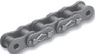 must be noted.
Abbreviations Utilized in Equations
N Amount of teeth around the significant sprocket.
n Amount of teeth to the small sprocket.
R Speed in revolutions per minute (rpm) on the big sprocket.
r Pace in revolutions per minute (rpm) on the tiny sprocket.
C Shaft center distance in chain pitches.
HP Horsepower rating with the drive motor or engine.
KW Kilowatt power rating of drive motor or engine if using metric units.
SF Services Factor
Roller chains are one particular in the most effective and value eff ective approaches to transmit mechanical energy involving shafts. They operate above a wide variety of speeds, handle large functioning loads, have incredibly small power losses and therefore are normally inexpensive compared with other solutions
of transmitting energy. Profitable choice consists of following many rather basic ways involving algebraic calculation as well as utilization of horsepower and service element tables.
For almost any provided set of drive disorders, there are a number of attainable chain/sprocket confi gurations that will efficiently operate. The designer therefore must be mindful of several fundamental selection rules that when utilized accurately, support stability general drive efficiency and expense. By following the ways outlined within this segment designers really should be capable to generate selections that meet the prerequisites on the drive and are cost eff ective.
Basic Roller Chain Drive Rules
? The proposed variety of teeth to the smaller sprocket is 15. The minimum is 9 teeth – smoother operation is obtained with additional teeth.
? The encouraged optimum quantity of teeth for that large sprocket is 120. Note that although extra teeth enables for smoother operation owning as well quite a few teeth prospects to chain jumping off the sprocket immediately after a reasonably modest volume of chain elongation resulting from wear – That may be chains with 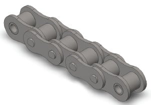 a extremely big quantity of teeth accommodate significantly less dress in before the chain will no longer wrap about them effectively.
? Speed ratios need to be 7:1 or much less (optimum) rather than greater
than 10:one. For bigger ratios the use of various chain reductions is advised.
? The proposed minimum wrap with the modest sprocket is 120°.
? The encouraged center distance in between shafts is 30-50 pitches of chain. You will discover two exceptions to this as follows:
one. The center distance needs to be better compared to the sum with the outside diameters of your driver and driven sprockets to stop interference.
2. For speed ratios better than 3:1 the center distance shouldn’t be less than the outside diameter of your substantial sprocket minus the outside diameter of the tiny sprocket to assure a minimal 120° wrap all-around the modest sprocket.
Any injury over the teeth surfaces of a sprocket diminishes the daily life of your conveyor chain.
With conventional sprockets, considerably worn sprocket teeth have been repaired by teeth padding or the complete sprocket was replaced. In both case, repair was pricey and with teeth padding, accuracy was impaired. We developed new sprockets with detachable teeth for independent replacement. This sprocket is extremely rated by our consumers for that dramatic savings in value and time.
Structure
The teeth is usually replaced by two techniques: personal tooth replacement or sectional teeth replacement.
The bolts and nuts utilized for mounting the teeth on towards the sprocket are spot-welded to prevent loosening.
The respective structures are illustrated about the ideal.
The above photo and also the best ideal illustration demonstrate a sprocket for person tooth replacement. Since the joint face amongst the replaced teeth plus the sprocket is formed within a unique arc, the bonding accuracy is high and the sprocket strength is enhanced. Furthermore, because the load acting over the mounting bolts is decreased, there is much less probability of loosening. This sprocket development is patented.
You will find two types of hubs: cast steel and welded sheet 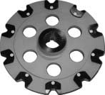 steel hubs. Cast steel hubs are used for significant sprockets getting hefty loads and welded sheet steel hubs for other applications.
For Use at Low-temperature
When utilizing conveyor chains at low-temperature this kind of as within a fridge or within a cold atmosphere, the following situations could take place.
1) Low temperature brittleness
Generally, a materials is embrittled at low-temperature and shock resistance is lowered. This phenomenon is called low-temperature brittleness, and the degree of embrittlement differs from material to material.
The services limit of the conveyor chain depends on its specs.
two)Influence of freezing
At low-temperature, bending failure, roller rotation failure, fixing of chain, and so on. can be brought on from the freezing of penetrated water or deposited frost from the clearance amongst pins and bushings, bushings and rollers or inner plates and outer plates. These circumstances lead to an overload to act on the chain and drive, diminishing the life on the chain.
To avoid freezing, usually, it truly is proposed to fill the clearances using a low-temperature lubricant ideal towards the support temperature to prevent water, frost, and so on. from penetrating the respective portions in the chain. For lubrication, a silicon based mostly grease is advised.
For Use at High-temperature
Chains power is diminished by  high-temperature environment, direct conveying of high-temperature loads, or radiated heat, and so forth. The support restrict at high-temperature depends not on the temperature in the services setting however the temperature and materials in the chain physique.
Following disorders may perhaps take place when chains are applied at high-temperature:
1) High temperature brittleness and fracture by lowered hardness of heat treated material
two) Brittleness triggered by carbide precipitation
three) Abnormal put on by scale
four) Fatigue fracture brought on by repeated thermal shock (cooling and expansion)
five) Abnormal dress in as a result of an increase from the coefficient of friction
six) Creep fracture
seven) Fracture as a result of thermal fatigue of welded place
8) Effects caused by thermal expansion
?Stiff backlinks and rotation failure as a result of decreased clearance ?Fatigue fracture resulting from lowered fitting force
9)Lubrication failure and stiff backlinks as a result of deterioration and carbonization of lubricating oil
Grease great in heat resistance involve individuals determined by silicon, graphite or molybdenum disulfide.
For use at high-temperature, high-temperature resistance bearings and stainless steel bearings are advised.
Generally, a chain is bent in transverse course only. On the other hand, a 3D Bending Conveyor Chain could be structurally bent not merely horizontally but in addition vertically. It is made use of to get a conveyor line  which moves vertically and adjustments in path.
X Sort Chains for Trolleys, and Energy & Free Conveyors
X-type Chains are utilized for trolleys, and energy & free conveyors. They are drop-forged rivetless chains featuring high strength, lightweight and easy removal of components. The bottom left photo shows an X-type Chain employed as a trolley conveyor with only one rail.
The bottom right photo shows an X-type Chain applied for a power & free conveyor. An additional rail is installed to receive the load for higher transfer capability.
A energy & free conveyor generally has a so-called stop and go function to connect and disconnect conveyed materials with and from the chain, so that the conveyed materials could be temporarily stopped, mixed and stored.
Three kinds of X-type Chains are available according to required strength.
Z-type Chain for Light Load Trolley Conveyors
A Z-type Chain for trolley conveyors is employed for service similar to that of X-type Chains described on the previous page, but is suitable for light loads. It’s widely applied in conveyors supplying parts, and devices for storing and unloading parts on automobile assembling lines.
Z-type Chain for Light Load Trolley Conveyors
A Z-type Chain for trolley conveyors is employed for service similar to that of X-type Chains described on the previous page, but is suitable for light loads. It is actually widely made use of in conveyors supplying parts, and devices for storing and unloading parts on automobile assembling lines.
FH Variety Chain for Freeyor
An FH Kind Chain is applied for the same purpose as an X-type Chain and Z-type Chain. While X-type Chain is designed for heavy loads and Z-type Chain is for light loads, FH Variety Chain is employed for intermediate loads. While X-type Chain and Z-type Chain might be vertically bent only slightly, FH-type Chain is often bent both vertically and horizontally, which makes it suitable to get a conveyor line moving vertically. We manufacture three kinds of FH-type Chains different in pitch.
Towline Low-Selec-Tow Chain
A towline conveyor has a mechanism to convey dollies caught by a chain buried in the floor. Our chain for towline conveyor is called LST chain (Low-selec-tow chain).
LST Chain could be bent horizontally and can also move on a slight incline. It’s made by forging, and a recess for hooking a dog is formed at the center of each link.
BF Variety Bushing Chain for Water Remedy Drive Unit
This chain is used to connect water therapy equipment to a electrical power source. From the previous,  JIS/ ANSI sort roller chains have been utilized. For enhanced corrosion resistance, all the components are now created of 13Cr stainless steel. Since the chain is operated at a slow pace, a bushing chain with out rollers is utilised. The sprockets are interchangeable with JIS/ ANSI roller chain sprockets.
We manufacture 7 varieties of BF Sort Bushing Chains in the vary from 120 to 240, like heavy-duty style.
Chains utilized for collecting accumulated sediment in setting basins and sedimentation basins or removing the collected sediment in sewage treatment method services together with other water therapy facilities demand in particular higher resistance to corrosion and dress in considering the fact that they are right exposed to sewage and sludge. A grime getting rid of chain is moved at a reasonably rapidly velocity on an almost vertically installed rail, although the operation frequency is low, so WS Kind Roller Chain is utilized. Conversely, a chain for raking up and/or out grime is driven at an incredibly slow velocity and will not require rollers, so WAS Kind Bush Chain is used.
Eighteen varieties of WS Sort and 6 varieties of WAS Sort Chain can be found.
(a) WS Style Roller Chain
A WS Form Roller Chain is created to supply high corrosion resistance and wear resistance for extended support in the extreme environment of water remedy applications.
Since the operating time of this type of gear is comparatively brief, pins and bushings of hardened stainless steel and various components are made of exclusive alloy steel to guarantee smooth bending of the chain, and fantastic wear and corrosion resistance.
(b) WAS Variety Bush Chain
Heat taken care of stainless steel presents this chain with fantastic performance for corrosion resistance and put on resistance.
Water Remedy Conveyer Chains can be found for your following 4 applications as normal.
Chains for Traveling Water Screen
A thermal power plant or nuclear electrical power plant requires in the substantial amount of sea water as cooling water. Sea water has several different residing organisms, this kind of as jelly fish and algae. A traveling water screen which frame is rotated by a chain removes impurities in the consumption port of sea water. Because the chain is used in sea water, resistance to corrosion and brittle fracture are distinctive style concerns. We’ve been energetic during the investigation, advancement and manufacture of submersible conveyor chains in the early days of their use.
It is a highly effective chain developed to get sufficiently resistant to corrosion, wear and impact so that it may serve the goal of getting rid of massive trash under serious ailments. It really is of the offset kind, which could allow lengthening and shortening in units of even a single hyperlink.
Rake Chain
Yet another machine made use of for that similar function since the traveling water display to take away sea water impurities is often a bar screen with rotary rakes. The display is intended to clear away impurities extra coarse than people eliminated  by the traveling water display. Impurities caught by a fixed bar screen are removed by rakes and discarded into buckets. A Rake Chain moves the rakes and buckets along the bar screen. Since the traveling water screen, resistance to corrosion and brittle fracture are primary style and design considerations.
Rake Chain utilized for bar display includes the elements made from stainless steel as well as hyperlink plate coated by using a distinctive synthetic resin, and it truly is really resistant to corrosion at the same time as dress in.
Whenever a chain owning 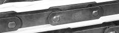 a high tensile strength for your chain width (corresponding on the pin length) is needed, a block chain is an superb preference. A Block Chain is simple and very rigid because it doesn’t have bushings or rollers. Whilst the frictional force is significant once the chain runs over the floor, the chain has an extended support existence as it has no rotating elements. Therefore, substantial loads is often conveyed. Block Chains are suitable for conveyors loading hefty articles or blog posts with sturdy impact and conveyors applied in serious environments to convey higher temperature or abrasion-sensitive and corrosion-sensitive objects.
We manufacture 26 varieties of typical Block Chains in tensile strength ranging from 308kN (=31.five tons) to two,721 kN (=277.5 tons). For enhancing dependability of conveyance, block chains with many canines are intended and manufactured upon request.
(a)Block Chain
DK Block Chain includes two outer link plates and a single block connected by pins. This exclusive development is very substantial in the two rigidity and mechanical power. Also excellent in wear resistance and heat resistance, it truly is suited for pulling articles too as for large pace conveyance and conveyance of high-temperature elements. Usually it is combined with different canines according on the sorts of resources to be conveyed, although it can be also probable to load elements straight around the chain or fit the chain with other types of attachments.
Kind of canines
one. Fixed puppy
A protrusion is offered on a block or outer plate for conveyance.
two. Tilt dog
A conveyed post in front from the dog is pushed by a canine, such as a fixed puppy. When a conveyed post comes from the rear or when the chain travels reversely, the dog is tilted forward, allowing the write-up to pass. Soon after the post has passed, the dog automatically returns to its unique position.
three. Duck puppy
A duck dog applies strain on a conveyed posting on the manual rail. In the position where the manual rail ends, the canine ducks (drops), leaving the posting at that position when passing underneath it.
four. Tilt duck puppy
A tilt duck dog has each the functions of the tilt puppy in addition to a duck dog. As it travels on the guidebook rail, it maintains pressure on the conveyed article. Whenever a conveyed short article comes from the rear, the canine tilts to permit it to pass. In the place exactly where the guide rail ends, it ducks to leave the posting at that position, while passing below it.
(b)Particular Rivetless Chain
The earlier part describes that by combining with various attachments, the DK Conveyor Chains can be used for nearly all standard applications. This part describes the DK Specialty Conveyor Chains formulated primarily based to the Typical Conveyor Chain. Specialty Conveyor Chains offer improved form, size series and materials strengths that suit respective applications. They could be classified into three types: Specialized Application Conveyor Chain, Water Treatment Conveyor Chain, and 3D Bending Conveyor Chain.
Conveyor Chain  with Attachments for Conveying Bulk Components
Constant Flow Conveyor Chain and Chain for Dust Conveyor
A chain with blades is operated inside a powder to lead to the powder to movement within the similar route as the feeding route on the chain. This really is identified as a Continuous Movement Conveyor Chain. The exact same sort of chain can be used in a similar way for discharging the dust produced by different dust collectors. We manufacture 25 forms of Regular Conveyor Chains with blades, two forms of Block Chains with blades , respectively appropriate for your several properties of dusts and powders, and five chains with unique cast steel blades for conveying powders more likely to result in put on. The respective chains are designated as follows:
We manufacture continuous flow conveyors and dust conveyors employing the over chains with blades as regular tools. Check with us for even further information.
(a) Continuous Flow Conveyor Chain
Steady Flow Conveyor Chains are utilised for our conventional continuous flow conveyors. Based on the conveyed subjects, the following three varieties of attachments can be found. The fundamental chain is often either a Conventional Conveyor Chain or possibly a Powerful H-type Conveyor Chain.
(b) Chains for Dust Conveyor
This chain is employed for conveyors solely for carrying dust. Depending on the application, the following 3 sorts are available:
one) Roller S Conveyor Chain for low density powder with Attachment B or B1 for U and LU Type Dust Conveyors
two) Roller M Conveyor Chain for medium density powder with Attachment KL or KUL for DU, DU-S, LDU and LDU-S Form Dust Conveyors
three) Block Chain for very abrasive powder with KL or KUL attachments for DUB, DUB-S LDUB and LDUB-S Style Dust Conveyors
You will find many different choice for heat therapy and specs for that conveyor chains. Particular remedies could be utilized not merely to the chain as being a whole but to each element individually, such as pins or plates only.
Select desired combinations in reference to the following explanation of options and uses.
Double Guard Coating
The surface is taken care of 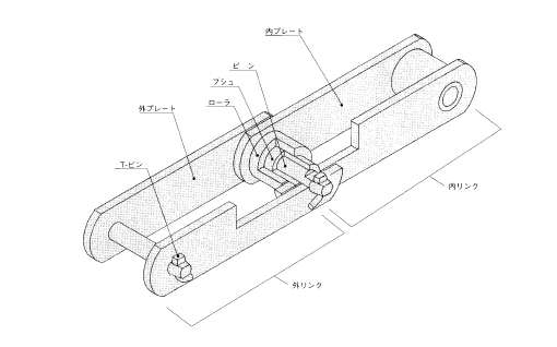 with excellent corrosion resistant coating that approaches the resistance of stainless steel. Double guard coating includes double layers of two distinct products. It exhibits virtually doubled corrosive resistance during the salt water spray check compared to our typical higher guard coating, and will be utilized in mild alkaline or mild acidic circumstances up to pH3.
With its enhanced corrosive resistance, it could be used in conditions exactly where higher guard or plated coatings cannot be used, and in many cases in some problems where only stainless steel might be applied.
(Double guard coating cannot be utilized to welded parts.)
Large Guard Coating
Substantial guard coated surface has excellent corrosion resistance.
The surface of the chain is finished in non-gloss white really protective coating. It has superb resistance to salt corrosion and rusting. This coating protects chains in large temperatures as it can resist heat as much as about 250°C.
Considering that large guard coating acts being a sacrificial anode for that chain body, it is possible to count on ample corrosion resistance even if the coating has come off to some extent. Also, it may possibly be applied to welded elements.
It is advised for outside use or close to the sea in situations where overall performance as higher as that of stainless steel isn’t required. In circumstances that call for resistance to alkaline and acid, double guard or stainless steel coating is recommended because they have improved resistance than substantial guard.
Plating
Plating is mainly carried out with nickel. It really is a coating with both interesting exterior and corrosion resistance. Through the use of it with grease lubrication, it exhibits fantastic corrosion resistance. It is possible to expect the effect to delay hydrogen brittle destruction when utilized in circumstances exactly where chains are exposed to sea breeze or acidic sprays.
(Double guard coating can’t be utilized to welded parts.)
DK Conveyor Chains are available inside a range of dimensions, roller kinds, and materials and heat treatment. Additionally, the chains is usually employed for any broad range of application with our extensive choice of attachments and additional characteristics.
Classified by Dimensions
DK Conveyor Chains may be classified into normal, robust H-type and robust Z-type with reference on the size from the base chain.
The Normal Conveyor Chain may be the standard form of DK Conveyor Chains, and many attachments, resources, heat therapies, etc. are available.
The Sturdy H-type Conveyor Chain was initially designed as being a chain for bucket elevators with enhanced strength and is now accessible inside a series. A small-sized Solid H-type Conveyor Chain is almost equal in strength to a large-sized Common Conveyor Chain, but since the dimensions and form differ, sprockets aren’t interchangeable. Usually, Strong H-type Conveyor Chains are larger in strength than Typical Conveyor Chains with in regards to the exact same roller diameter.
Strong Z-type Conveyor Chains are more enhanced in strength than Strong H-type Conveyor Chains by elevating the height in the inner plates, along with the sprockets are interchangeable when the nominal quantity is the same. Robust H-type Conveyor Chains are utilized in machines through which the plates slide within the floor, this kind of as steady movement conveyors, since the inner and outer plates possess the exact same height.
However, Strong Z-type Conveyor Chains exhibit higher fatigue strength and therefore are utilized in vertical conveyor bucket elevators.
Classified by Roller Form
The rollers of the conveyor chain perform not simply to engage the sprockets moving the chain but also to rotate and travel on a rail, conveying articles or blog posts with smaller frictional reduction. To meet different shapes of rails and prevent meandering, and so on., 4 sorts of rollers, substantial roller, flange roller, medium roller and small roller.
Furthermore, for smoother rotation, we give massive rollers and flange rollers with built-in bearings (BR and BF rollers, respectively), and UR and UF rollers with massive clearances amongst the bushing as well as the roller to stop the entry of foreign matters into the bearings. These rollers tend to be utilized in waste processing services.
In this catalogue, huge rollers, flange rollers, medium rollers and tiny rollers are respectively expressed as R-roller, F-roller, M-roller and Roller S.
Calculation of Chain Tension
Usually, in the beginning, tentatively determine the chain dimension for being utilized referring to “Tentative determination of chain size”. Then, obtain “Theoretical chain tension (T)” (P213) for the tentatively determined chain, and multiply the value by “Speed coefficient (K)”, to get “Substantial chain tension (Ta)”. For safety, the considerable chain stress has to be reduced compared to the “maximum allowable tension” stated inside the table of dimensions of respective chains. Consequently, the affliction beneath really should be satisfied.
Safety situation of chain tension
Substantial chain tension (Ta) =Theoretical chain tension (T) ×Speed coefficient (K)
Considerable chain tension (Ta) <Maximum allowable stress
If this affliction will not be content, select a larger chain by a single dimension and re-calculate.
Tentative determination of chain dimension
qDetermine the mass (excess weight) per unit length of parts this kind of as chain and attachment ωc (kg/m or kgf/m) assuming that it can be 10 percent of your mass (weight) of your conveyed object ω1 (kg/m or kgf/m).
wIn reference for the calculation formulas on, acquire “Theoretical chain tension (T)” (kN or kgf) and “Speed coefficient (K)”, and calculate “Substantial chain tension (Ta)” (kN or kgf).
eIn reference to the table of dimensions of chains,identify the minimum chain, whose “maximum allowable tension” is increased than the “Substantial chain tension (Ta)”, and regard it as “tentatively determined chain”.
Value of pace coefficient (K)
The speed coefficient (K) expresses the severity of operation affliction according to your traveling pace of chain because the situation turns into severer because the traveling pace of chain turns into 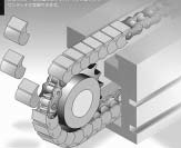 increased.
Multiply “Theoretical chain tension (T)” by “Speed coefficient (K)” to get “Substantial chain tension (Ta)”.
After you design and style many conveyor systems making use of small conveyor chains, the following basic circumstances need to be happy.
a. Chain tension: The actual tensile power in operation have to be significantly reduce compared to the specified strength of your chain.
b. Strength of loaded components of chain: The actual loads utilized to attachments, this kind of as rollers of base chain, top rollers, side rollers, etc. in operation has to be considerably smaller sized than the power of those components.
c. Wear life of chain: Lubrication disorders to make certain the dress in existence of chain need to be fulfilled.
d. Sag adjustment of chain: The sag with the chain have to be kept optimum by stress adjusters, take-up devices, guides, and so on.
e. Other individuals: Acceptable measures are taken to avoid rail dress in, machine vibration and also other problems.
The following complement the above.
A DK conveyor chain includes a construction, along with the names on the parts are stated inside the drawing. These components have functions specified beneath.
Pins
Pins support each of the load acting around the chain along with plates, and once the chain is engaged with all the sprockets, they slide along with bushings as bearings. They are topic to wear and particularly ought to have large shear power, bending power and put on resistance. Hardened and tempered challenging steel, carburized steel, or induction-hardened steel is used.
Rollers
Rollers guard the chain from shocks with all the sprockets, and when the chain is engaged with the sprockets, the rollers bend the chain smoothly and act to reduce the resistance when the chain runs on a rail. These are needed to possess higher shock fatigue strength, collapse power and dress in resistance. Hardened and tempered hard steel, carburized steel or induction-hardened steel is utilised.
Bushings
Bushings are found concerning pins and rollers and act as bearings for both the pins and rollers to not transmit the load received by the rollers directly for the pins once the chain is engaged together with the sprockets. They’re needed to possess large shock fatigue power, collapse strength and put on resistance, and on the whole, carburized steel is used.
Plates
Plates are subject to repeated tension from the chain and from time to time to significant shocks. They are really demanded to have substantial tensile power, and particularly higher shock power and fatigue power. Substantial tensile steel is made use of for standard chains and heat-treated alloy steel for heavy-duty chains.
T-pins
T-pins reduce the outer plates from disengaging in the pins. They can be made from soft steel because pins are commonly pressed-in the outer plates and so no big force acts to the T-pins.
Single pitch chain
This chain is linked by hollow pins, plus the hollows might be used to attach several attachments. In hollow pin chain, the hollow pins are the exact same since the bushings with the corresponding standard chain in diameter, so hollow pin chain is usually thought to be bushing chain that incorporates bushings from the similar diameter as that of your rollers on the corresponding common chain.
Standard sprockets may be utilised.
The connecting links are particular snap ring types for hollow pin chain as illustrated.
Considering that no offset website link is available, the quantity of back links really should be an even number.
Versatile Chain
Flexible Chain has great sideward bending flexibility and is appropriate for curved traveling. Sprockets for JIS/ANSI Common Roller Chain is usually made use of for this chain. By fixing attachments, this chain could be utilised for curved transfer with conveyors.
Flat Style Roller Chain
This chain is suited for conveyor techniques because it has flat plates that lead to little damage to elements this 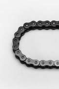 kind of as chain guides. (The kinds of outer plates and inner plates are the same.)
Top Roller Chain
Loads could be straight positioned over the top rated rollers. By attaching a stopper within 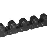 the conveyor, loads might be temporarily stopped or stored though continuously driving the chain.
Side Roller Chain
This chain is applied to get a free of charge flow conveyor that runs on rails, and also the side rollers carry the weight of loads. Compared with Leading Roller Chain of the similar material, it might carry heavier load.
Hollow Pin Chain (HP)
The chain is linked with hollow pins that could be used for fitting numerous attachments.
Flexible Chain (FX)
This chain has much sideward bending versatility and it is ideal for curved traveling.
Flat Plate Sort Roller Chain (F)
Damage to chain guards and other components are reduced with the use of oval-shaped flat plates, and loads might be set directly around the chain.
Push Chain(PU)
This is the primary chain that has the capability to push. New layouts are doable because loads is usually pushed and pulled with out applying the guide, and area can be saved in comparison to the use of cylinders.
Usually, conveyor chains are operated for longer distances and at lower speeds than transmission chains. Accordingly, even though the pins, bushings and rollers are left unchanged, and the plate pitch is doubled to reduce the quantity of sprocket teeth engaged together with the chain to half, the wear of pins, bushings and rollers is small since the chain velocity is lower. Double Pitch Chains, conform to ANSI regular and “Ultimate Lifestyle Chain Series” and “Environment Resistant Chain Series”, as are single pitch chains may also be available.
Double pitch chain with resin rollers
This can be a Double Pitch Chain with R Roller made from resin, which generates much less noise and lighter fat in contrast with steel rollers. So, the chain is ideal for any conveyor technique intended to operate quietly and convey light-weight articles or blog posts. Since the parts aside from rollers are made of steel, the common tensile power of the resin roller chain will be the very same as that of a steel roller chain. Nevertheless, the “maximum allowable load” of your chain really should be kept decrease, as proven in the following table, to prevent injury to your plastic rollers through the strain from the engagement with sprockets.
The “Allowable load of resin rollers” refers towards the allowable load acting when conveyed content articles press the resin rollers traveling on the floor surface this kind of as guid rails.
Large roller (R) and modest rollers (S)
Considering the fact that double pitch chains are 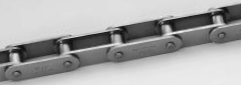 frequently made use of for conveying solutions on the horizontal floor, chains designed for this purpose have improved roller diameter equal to that of single pitch chains from the exact same pitch for improved load capacity and reduced traveling resistance. These rollers with more substantial outer diameter are called “large rollers”, as well as the typical rollers are named “small rollers”.
In this catalog, substantial rollers are expressed as R Roller, and little rollers as S Roller.
Designation of double pitch chains
A double pitch chain is designated, as while in the following example, depending on the nominal variety of the single pitch chain it is actually determined by.
Connecting hyperlinks
For the connecting links of double pitch chains of all sizes, the connecting plates and connecting pins are clearance-fitted. For C2060H or smaller, the spring clip kind (R connecting website link) is typical. For C2080H or more substantial, the cotter variety (C connecting link) is typical. Connecting links with an attachment, top roller or side roller are also available.
For ” Smaller Conveyor Chains”, many hyperlinks are available for coupling and attaching customized devices straight for the chains. These backlinks are identified as attachments. The next typical attachments are available.
Varieties and names of regular attachments
standard attachments incorporate 5 kinds for single pitch chains and 5 types for double pitch chains as illustrated below. On top of that, for single pitch chains, 4 varieties of wide attachments, as wide as outer plates, can be found. Standard attachments for respective chain sizes are listed around the following webpage.
How you can indicate the specially organized chains with attachments
A chain with 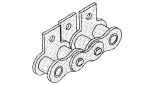 Attachment K1s specially arranged as over is indicated as follows:
CJ+(K1 inner+PL)×3+3LL+PL+(K1 inner+PL)×3+3LL+K1 outer+(RL+K1 outer)×2+5LL
“CJ” stands for a C connecting hyperlink; “K1 inner”, an inner website link Attachment K1; “PL”, an outer website link; “3LL”, three backlinks from an inner link to an inner website link; “K1 outer”, an outer link Attachment K1; and “RL”, an inner link, respectively. A “+” sign implies “connection”, and also a “×” indicator means “repeat”. (For one-side attachments such as Attachment A and Attachment SA, the position of attachment plates is on side A from the over illustration.)
Note: When attaching attachments to each even-number link, they are really attached to outer hyperlinks, unless of course specified.
Ultimate Lifestyle Chain Series
Reliable Bushing (HT/ T), (D)
1.Utilizing substantial precision solid bushings
two.Greater put on resistance than standard chains
three.Dress in existence is improved by one.2 to four times of regular chains
DH-|¨¢(DHA)
1.Ultra hardening coated pin surface
2. Appropriate for conditions where foreign substance contamination or extreme oil degradation occurs
three. Put on life is improved by one.2 to 7 occasions of regular chains
O-Ring (LD),X-Ring (LX)
one. Grease is filled concerning pins and bushings.
two. High-end product or service of Greatest Existence Chain that could be made use of anywhere
three. Dress in life is enhanced by five to twenty times of typical chains
Sintered Bushing (UR), (URN)
1.Utilizing sintered alloy for bushings
two.Extended life chain for low-speed and light load operation
three.Dress in life is improved by five instances of  common chains
Nickel Plate(N)
one.Specialized nickel coating
2.Appropriate for situations requiring a clean impression and neat appearance
three.Withstands salt breeze and acidic conditions
Surroundings Resistance Chain Series
Hi-Guard
one.High corrosion resistance coating
two.Ideal for conditions both indoors and outdoors in which long-term resistance to rusting is equired
3.Outstanding resistance to corrosion, salt and rusting
Double Guard (WG)
1.Approx. twice a lot more corrosion resistant when compared with Substantial Guard Chain
two.Applicable in mildly acidic or mildly alkaline situations
3.Downsizing is attainable compared to Stainless Steel Chain
Stainless Steel Chain:SS
one.18-8 stainless steel
2.Appropriate for circumstances exposed to chemical agents, water or higher temperature
three.Most effective corrosion resistance and heat resistance
Stainless Steel Chain:SSK
one.18-8 stainless steel (plate) + precipitation hardened steel (pin/ bush/ roller)
2.Suitable for places exposed to chemical agents, water and high temperature
3.one.five instances far more allowable tension when compared with SS type
Stainless Steel X-Ring Chain (SSLT)
1.Superb wear resistance
two.Outstanding expense overall performance
3.Significant reduction in friction-loss
Minimal Temperature Resistant Chain (TK)
1.Using material appropriate for reduced temperature and specialized grease
2.Ideal for conditions exactly where temperatures drop right down to -40 ??C.
three.Superb very low temperature strength
In case the engagement among chain and sprockets turns into defective or any component that causes excessive decline inside the power of 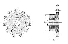 the chain takes place, change the whole chain. When any from the following circumstances arise during the chain you employ, change the entire chain to maintain safety.
When a chain is worn near to the “Elongation restrict of chain” .
?Whenever a flaw or crack happens in a plate.
?Whenever a flaw or crack or defective rotation of a roller is observed.
?When a chain link is stiff.
?When a pin is rotated.
?When a pin is bent or otherwise deformed or whenever a plate is critically warped.
?When rust buildup prevents smooth bending from the chain.
?When diluted sulfuric acid or any other corrosive material is deposited.
In the event you cannot judge regardless of whether a flaw is “harmful”, please seek advice from us.
Replacement of sprockets and how to buy
The existence of sprockets is generally various instances the life of the chain, but if the teeth are worn for the reason that of inadequate lubrication or damaged simply because of a shock load, etc., the sprockets has to be replaced.
?When placing an buy, please specify the following if your chain No. is regarded.
one. Chain No. and amount of strands
2. Type of sprockets
3. Shaft hole diameter (d) (This is certainly not important for those who drill this hole; in this case, drill a hole not exceeding the maximum shaft hole diameter.)
four. Number of teeth
five. Hub diameter (DH) and length (L) (within the situation of non-standard sprockets)
6. Whether the tooth heads are hardened
Specify the next objects, when the chain No. is unknown
1. Tooth thickness (T)
2. Root diameter (DB) (Caliper diameter (DC) inside the situation of odd-number teeth)
Necessity of lubrication
Inside a roller chain transmission, even if the chain and sprockets are developed to suit the service circumstances, bad lubrication inhibits maintaining overall performance and existence to design specifications. Inside the case of a roller chain, the wear reduction caused beneath suitable lubrication is significantly different from that triggered with out it. Troubles caused as a result of inadequate lubrication consist of the wear of pins and bushings, rough engagement together with the sprockets, greater noise, and breakage because of prolonged undesirable ailments. Good lubrication is extremely vital. Needs of lubrication as well as effects of appropriate lubrication are listed below.
Selection of lubricant
Lubricant should be a mineral oil of excellent top quality. It can be critical the lubricant has no dust or foreign substance. Under no circumstances use waste oil. Should the ambient temperature is very reduced (-10??C or reduced) or substantial (+60??C or increased), a specific oil is necessary. In this instance, please talk to our engineering division.
Lubricating factors
If the chain is immersed in an oil bath, oil penetrates every aspect on the chain. Inside the situation of manual lubrication, brush lubrication or drip lubrication, make certain that the oil sufficiently penetrates the portions of q and w within the following illustration.
Lubricate on the sag side from the chain, i.e., with the position indicated in the following illustration. Since the lubricant can also be valuable for rust prevention, coating the whole surface of your chain using the oil is recommended.
Lubrication forms (Explanation of the, B and C inside the tables of Drive functionality (kW ratings)
The allowable kilowatt ratings of chains proven in table in the drive functionality (kW ratings) is based mostly about the issue that any from the following lubrication is adopted.
General cautions for lubrication
Unless of course good lubrication is carried out, chain fatigue will result earlier, leading to various difficulties. Careful inspection is necessary.
From the situation of inadequate lubrication
In the event the lubricant is exhausted, red rust is created involving the inner and outer plates, causing put on drastically. When a chain is disassembled after going below such issue, red rust is visible on the surfaces of pins, and also the surfaces are roughened, as shown within this photograph. (Usually, pins possess a mirror surface.) The lubricant needs to be applied prior to this happens.
Tend not to use grease for lubrication !!
Will not use grease to lubricate your chains, due to the fact grease will take also extended to reach the within via pins and bushings at ambient temperature.
Just before lubrication, get rid of foreign substances and filth through the chain as totally as you can. If water is utilized for washing the chain, swiftly dry it to prevent rusting, and  then lubricate.
While in the situation of drip lubrication, oil bath lubrication or forced feed lubrication
Check the next:
one. The lubricant is not dirty.
2. The level of lubricant is accurate.
three. Lubricant is uniformly applied to your chain.
Cautions
Dust contamination should be avoided to retain put on resistance. If temperature rises abnormally or even the chain squeaks, the oil may possibly be exhausted. Check out to verify the issue.
Check out
a.Verify the next before operation
Connected joint
Confirm the connection is enough and that elements have no problem.
Verify that bending is smooth(from the situation of O-ring chain, bending is somewhat stiff).
Chain sprocket attachment
Verify that there’s no severe flaw, rust or wear.
Verify that sag is good.
Confirm that no pin rotates.
Verify that rollers rotate smoothly.
Confirm the chain engages with the teeth of sprockets.
Interference
Verify that there is nothing at all interfering together with the chain, or that practically nothing is likely to interfere with all the chain or safety cover.
Lubrication
Verify that the amount of lubrication is appropriate. (For your sum of lubrication, see the table of lubrication styles.)
Driving and driven shafts
Confirm that the axial measurement and parallel measurement are correct.
Verify the difference of sprocket planes is within the allowance.
Peripheral products
Verify that peripheral gear is set up properly.
b.Just after confirmation and adjustment with the over a, set up the security cover, and switch about the electrical power to start out operation.
?It’s doable to the chain to get thrown really should it break.Never keep in the route of rotation throughout operation.
Caution
Obstacles
?Obstacles might induce breaking or fracturing which might scatter materials and injure people today close by. You should definitely eliminate all obstacles.
Abnormal noise
?Abnormal noise all through operation is usually a signal of problems. Immediately switch off the power, and establish the cause.
Flaws and rust
?If any significant flaws or rust is visible, it might  induce the chain to break and fracture and possibly injure people today close by. Verify that the chain has no serious flaws or rust.
Sprocket
?If a sprocket is worn, the sprocket could break, or the chain could ride more than the sprocket, breaking it and perhaps leading to damage to folks nearby. Verify that the sprockets will not be worn.
Devices that avert accidents
?Install accident prevention gadgets.
To prevent human damage attributable to scattered supplies, install safety devices (safety cover, security net, and so forth.).
?Set up an emergency cease device.
In order to avoid human injury due to unexpected overload, set up an emergency shutdown device such as a load controller or possibly a brake.
Prior to trial operation
Confirm the following on chain installation prior to starting operation.
?The chain properly engages with all the sprockets.
?The joints are regular. (The spring clips are properly
put in and cotters are certainly not bent.)
?The chain sag is correct.
?The chain is just not in get hold of with the chain situation.
?The lubrication is proper.
Test goods in the course of trial operation
When the chain can be manually rotated, rotate it to confirm that there is no abnormality prior to starting up trial operation. Be alert to the following for the duration of trial operation.
?No matter if there exists abnormal noise.
Should the chain contacts the chain situation or when the chain heavily vibrates, abnormal noise takes place. Check out the set up of chain case and chain sag.
?Irrespective of whether lubrication is standard all through operation.
Re-check the situation of lubrication.
Elongation restrict of chain Restrict of Chain Sag
?Elongation restrict of chain
Even though sag adjustment is regular, excessive elongation in the chain may cause abnormalities much like those caused by sag failure that inhibit smooth transmission. In such scenarios, replace the chain. A guide for replacement depending on chain elongation limit is listed below. Whether or not only one website link reaches the elongation restrict, change the entire chain that has a new 1. Unless of course lubrication is standard, the chain will elongate promptly, creating the aforementioned troubles. Study the contents of “Lubrication” within the upcoming area thoroughly for doing appropriate maintenance.
?Elongation measuring approach
1.To get rid of rattling aside from a slight amount of play inside the chain like a total, tighten the chain lightly and measure the elongation.
Note: For an accurate measurement, measure the elongation in the chain applying a measuring load (specified by ANSI) to your chain.
two.As illustrated under, measure the inner length (L1) as well as outer length (L2) and acquire the measured length (L).
three.Then, receive chain elongation.
So as to cut down the measuring gap, measure the length of about six to ten back links.
Chain wear-elongation test gage
Sag adjustment of roller chain
To utilize a roller chain for any longer period of time, proper sag is a crucial element. If your roller chain is over-tensioned, the oil movie involving pins and bushings is misplaced, shortening chain lifestyle and damaging the bearings. In the event the chain sags overly, the chain will vibrate or be seized from the sprocket. In about 50 hours (it differs depending on the services problems) immediately after starting up the roller chain use, the chain is going to be elongated by about 0.1 percent from the total length on account of the conformability of respective contacts. So, alter the sag at this time. Thereafter, if proper lubrication is maintained, the elongation is going to be negligible. Check out and change the sag at good intervals.
Optimum sag
Normally, retain sag S at about 2 % of span L, but from the situation described below, retain it at about 1 percent.
How you can alter sag
Adjust sag while in the following strategies.
one.Adjustment of the center distance
two.Adjustment using a tensioner or idler
three.Increase or decrease of pitch number by offset link
four.Through the use of an offset link, the total length of a chain is often enhanced or decreased by one pitch. Nevertheless, considering the fact that offset website link overall performance is generally poor, an even amount of back links, if doable, is encouraged.
one.A connecting website link of an O-ring Chain for standard application is pre-coated with grease on the pins. Before connection, confirm the grease around the surfaces of pins, and should the level of grease is modest, apply grease with bare hands. (If gloves are used, the grease is going to be absorbed from the gloves.)
Illustration: Once the connecting hyperlink (I) of an O-ring chain for standard application is
shipped, O-rings are fitted in the roots from the pins. If your O-rings come loose as a consequence of vibration throughout transport, refit the O-rings in on the roots of the pins.
In this instance, make sure to return the grease collected on the roots of the pins for the central surfaces with the pins, far more at portion A than at portions 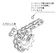 B proven from the above illustration. (Portions A is worn on account of sliding together with the bushings.)
2.The chain can be most effortlessly linked over the teeth of a sprocket. Engage the links at both ends with the chain with all the sprocket teeth and fit connecting pins. When the sprocket is often moved, the chain may also be connected within the loosened side.
3. Connecting method
one.Verify that O-rings are connected to your roots on the pins.
two.If your amount of grease utilized about the connecting pins is compact, coat the pins with grease with the central portions.
three.Insert the connecting pins in to the bushings of the inner backlinks at both ends.
4.Verify the grease is applied to your complete encounter from the O-ring, and match the O-ring onto the connecting pins.
five.Insert the connecting pins in to the connecting plate and even though pressing the connecting plate, install the spring clip. Confirm no matter whether the head (the end without a split) of the spring clip is turned while in the feeding course of the chain. (See the next illustration.)
six.You’ll want to confirm the spring clip is securely fitted inside the clip grooves of the connecting pins.
This completes jointing from the connecting hyperlink. Note that grease within the surfaces of connecting pins and O-rings might be eliminated all through installation perform. In this instance, re-grease using the grease about the surface from the base chain or even the grease in the polyethylene bag by which the connecting hyperlink was contained.
Installation of sprockets
For smooth transmission and extended daily life on the roller chain, it truly is crucial to the right way set up proper sprockets. Use the following set up process.
one.Adequately set up a sprocket on the shaft, and fix it that has a essential to stop it from rattling in the course of operation. Also, area the sprocket as close as you possibly can to your bearing.
2.Change the shaft levelness to ?¨¤1/300 or less working with a degree.
three.Alter the shaft parallelism[(A¡ê-B)/L]to ?¨¤1/300 or much less.
four.Change the level of driving and driven sprockets applying a linear scale. (Also adjust the idler and also the sprockets, or the tensioner as well as the sprockets from the very same way.)
Keep the allowance |? within the variety specified.
Set up of roller chain
When connecting a roller chain using the sprockets, observe the following procedure. Once the connecting link just isn’t properly lubricated, apply adequate grease.
When using the sprocket teeth
one. Engage the chain together with the sprockets to ensure the two ends with the chain are on one of several sprockets, as proven within the following photograph.
two. Insert connecting pins with the joint.
three. Match a connecting plate, and fasten by a spring clip or cotters.
Shell out additional awareness not to damage the tooth heads of the sprocket.
When working with tools
Cautions
1.Whenever a connecting plate is fastened by a 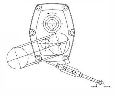 spring clip,apply the spring clip to the pin grooves from the connecting pins as illustrated under, and lock it applying pliers, and so forth. As for your course of spring clip insertion, preserve the opening on the spring clip turned during the route opposite to your route of chain rotation, as illustrated under.
2.In conditions wherever the sprocket center distance can hardly be adjusted, an odd amount of links may be utilised. Having said that, add a single hyperlink, to work with an even amount of links and eradicate the sag by shifting a sprocket or putting in an idler.
When an H-connecting website link is made use of, pins need to be driven in to the connecting plate due to the fact of interference. In this case, make sure that the pair of pins are stored parallel to every single other when inserted in to the connecting plate. Never make the holes from the connecting plate larger or make the pins thinner for simpler connection function. This applies also when a cotter style outer link (CP) is utilised in lieu of a connecting website link.
When a roller chain is utilised, shaft positions might be arbitrarily established. Having said that, in principle, follow the illustration proven beneath. That is certainly, in the event the chain is tensioned horizontally, maintain the top rated tensioned. Stay clear of vertical transmission anytime doable. In an inevitable situation, place the large sprocket with the bottom regardless 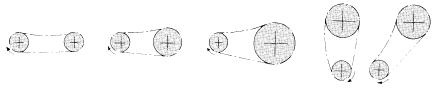 on the route of rotation.
When the chain layout is undesirable:
?When the best is sagging as well as sprocket center distance is brief:
As illustrated under, modify the sprocket center distance shaft to do away with the sag.
?When the top rated is sagging and the sprocket center distance is prolonged:
As illustrated below, set up an idler from inside to eliminate the sag.
?When the chain is vertical or inclined:
Eradicate the extra sag by a tensioner. In this instance, a tensioner that instantly eliminates the sag gives much better outcomes.
When a pulsating load acts in substantial velocity operation:
The chain’s vibration as well as the load influence frequency or chordal action may synchronize to amplify vibration around the chain. Considering that vibration influences the chain, consider countermeasures to prevent vibration in the following measures:
?Change the chain speed.
?Increase chain stress. Having said that, note that over-
tensioning can shorten the life in the chain. ?Use an idler or tensioner to divide the span
?Set up a guidebook stopper to prevent vibration.
Note: Chordal action refers to the vertical motion of chain brought about when it really is engaged with sprockets.
Needed length of roller chain
Employing the center distance concerning the sprocket shafts as well as quantity of teeth of each sprockets, the chain length (pitch amount) is usually obtained from your following formula:
Lp=(N1 + N2)/2+ 2Cp+{( N2-N1 )/2π}2
Lp : Overall length of chain (Pitch quantity)
N1 : Number of teeth of little sprocket
N2 : Variety of teeth of substantial sprocket
Cp: Center distance amongst two sprocket shafts (Chain pitch)
The Lp (pitch number) obtained from the above formula hardly becomes an integer, and usually incorporates a decimal fraction. Round up the decimal to an integer. Use an offset website link should the quantity is odd, but decide on an even amount around possible.
When Lp is 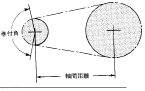 determined, re-calculate the center distance concerning the driving shaft and driven shaft as described inside the following paragraph. Should the sprocket center distance can not be altered, tighten the chain utilizing an idler or chain tightener .
Center distance in between driving and driven shafts
Of course, the center distance among the driving and driven shafts should be extra than the sum in the radius of both sprockets, but in general, a good sprocket center distance is regarded to be thirty to 50 instances the chain pitch. However, if your load is pulsating, 20 instances or significantly less is appropriate. The take-up angle between the small sprocket as well as chain should be 120°or much more. If your roller chain length Lp is given, the center distance amongst the sprockets is often obtained from your following formula:
Cp=1/4Lp-(N1+N2)/2+√(Lp-(N1+N2)/2)^2-2/π2(N2-N1)^2
Cp : Sprocket center distance (pitch variety)
Lp : Overall length of chain (pitch amount)
N1 : Variety of teeth of compact sprocket
N2 : Number of teeth of significant sprocket
This is a chain choice technique taking deterioration of power in relation to temperature into consideration. Please use suitable lubricant to the temperature at which the chain is always to be utilised. Check with us for information.
one. Effects of temperature around the chains
1.one Results of substantial temperature
1) Increased wear induced by lessen in hardness
2) Increased elongation triggered by softening
three) Lubricant degradation, defective flexion caused by carbonization
four) Increase in put on and defective flexion brought on by improvement of scales
2. Kilowatt ratings according to temperature
1.2 Effects of lower temperature
1) Decrease in resistance to shock brought on by minimal temperature brittleness.
2) Defective flexion triggered by lubrication oil coagulation.
3) Defective flexion induced by adhesion of frost and ice.
4) Rusting brought about by water-drops.
three. Chain Variety according to Temperature
(Chain speed=50m/min or significantly less)
four. Use of Stainless Steel Chains (SS, SSK) at higher temperatures
Stainless steel chains (SS, SSK) might be applied up 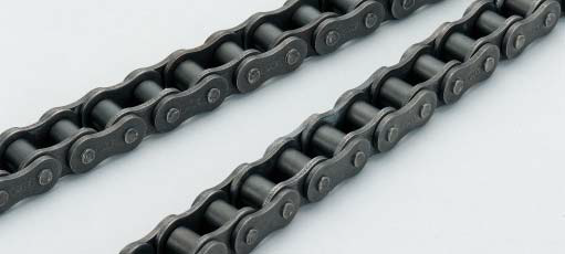 to 400??C, but be aware that the ambient temperature and also the chain temperature may well vary. The strength with the chain decreases as the temperature rises. Specially at high temperatures, the greater the temperature rises, the chain will rupture by a reduced load (creep rupture).
Furthermore, defective flexion or defective chain revolution happens because of heat growth. In an effort to prevent this kind of complications, adjust the clearance concerning chains. Consult us when employing chains at 400??C or larger.
Chains are unable to be made use of at 700??C or higher.
The description on this chapter is often applied whenever a chain is endlessly engaged for transmission with two sprockets parallel within their shafts and accurate in Driven alignment as illustrated below.
one.Consult us when a chain will be to be used for lifting, pulling dollies or becoming engaged which has a pin gear, and so forth.
two.When you’ll find any rules or recommendations regarding the variety of chains, pick a chain in accordance with this kind of laws plus the maximum kilowatt ratings (Drive effectiveness) table described under, and opt for the one with a greater allowance.
The chain is usually chosen in accordance with the following two procedures:
(one) Selection by drive performance
(2) Low-speed choice
The drive functionality process considers not simply chain tension but additionally the shock load over the bushings and rollers as a result of the engagement involving the sprockets along with the chain, as well as the wear of pins, bushings and rollers.
The slow-speed technique is applied when the chain is operated at a speed of 50 rpm or significantly less. Usually, the chain picked by this strategy is topic to ailments more severe than that selected according to the variety by drive effectiveness. Consequently, very carefully assess the conditions when selecting with this particular method.
Selection by drive efficiency
1st, the following info is required.
one.Power for being transmitted (kW)
two.Speeds of driving shaft and driven shaft (speed ratio) and shaft diameters
three.Center distance in between driving shaft and driven shaft
(a) Correction of electrical power to be transmitted (kW)
Correction have to be made to obtain the actual energy to become transmitted since the level of load fluctuates based on the machine and energy supply applied, affecting the expected services daily life (by way of example, 15,000 hrs within the case of capacities proven from the table of optimum kilowatt ratings). The support issue proven in Table one is definitely an indicator on the load degree. The energy for being transmitted (kW) is multiplied by the corresponding service aspect to acquire a corrected power.
Corrected power (kW) =
Energy for being transmitted (kW) ×Service element
(b) Choice of chain dimension and also the number of teeth of smaller sprocket
Making use of the table of optimum kilowatt ratings
If your final results tentatively determined as described over are near towards the design and style values, the number of teeth of small sprocket might be finalized with reference on the table of maximum kilowatt ratings. The utmost kilowatt ratings are established anticipating that an countless chain with one hundred back links features a daily life of 15,000 hours beneath the following situations. (That is definitely, the breaking in the chain as well as reduction of bushings and rollers will not come about at a dress in elongation of 2 percent or significantly less.)
one.Operation is carried out in ambient temperature (-10°C~+60°C) no cost from dust and dust-containing liquid.
2.There’s no corrosive gasoline, or humidity, and so forth. to adversely have an impact on the chain.
three.Right lubrication is maintained.
4.The chain is utilized under problems of the minimal start-stop frequency plus a relatively steady load.
Inside the situation of multiplex chain
Decide on a multiplex chain when the capacity of the simplex chain is inadequate. The utmost kilowatt rating of a multiplex chain can’t be obtained by multiplying the maximum kilowatt rating of a simplex chain by the variety of multiplex chain given that the loads are usually not evenly distributed involving the strands. To the correction issue on this situation, see the multiplex chain issue table. Our normal HI-PWR-S Roller Chains and HI-PWR-SHK Roller Chains are available as much as triplex.
Remarks for determining the number of teeth of compact sprocket
When a chain of your minimum chain pitch essential greatest kilowatt rating is chosen, reasonably silent and smooth transmission could be attained, plus the equipment is usually compact.
However, contemplating smooth chain transmission, the wear in the chain and sprockets, and so forth., it can be desirable that the sprocket have 15 or more teeth, and preferably an odd variety. Stay away from 12 teeth, 14 teeth and 16 teeth. Once the sprocket has 12 or much less teeth, the chain and sprocket heavily vibrate and therefore are incredibly worn, and transmission is not really smooth. Likewise, stay clear of a compact amount of teeth around doable except while in the situation of reduced velocity without having shock.
Shaft diameter
Following the amount of teeth of compact sprocket is established, multiply it by the velocity ratio, and confirm whether the required shaft bore is often secured in reference to the maximum shaft bore from the table of sprocket dimensions. If the needed shaft bore is more substantial compared to the highest shaft bore, increase the amount of teeth, or pick a a single dimension greater chain.
(c) Variety of the amount of teeth of substantial sprocket
When the amount of teeth of compact sprocket is established, multiply it by the speed ratio to find out the quantity of teeth of huge sprocket.
Normally, escalating the sprocket teeth amount can make the chain bending angle smaller, which increases durability and enhances transmission efficiency. Nonetheless, in case the amount of teeth is also big, slight elongation tends to lead to the chain to trip more than the sprocket, so retain the utmost quantity of teeth at 114 or less.
Speed ratio
A speed ratio refers to the ratio from the velocity of your driving shaft to your pace with the driven shaft, and commonly a speed ratio of 7:1 or less is risk-free. Should the velocity ratio is bigger than this ratio, the take-up angle of the chain on the modest sprocket decreases, and chain jumping or abnormal wear of sprocket are likely to take place. If a substantial speed ratio is necessary, two-step speed adjust might be important.
Low-speed variety
The low-speed selection process is utilized once the chain operation speed is 50 m/min or much less and there is no be concerned of wear elongation and shock fracture of rollers and bushings.
In low-speed choice, the chain is chosen in reference to your tensile fatigue strength with the chain. For that reason, a chain chosen in line with this method will likely be topic to far more extreme circumstances than one chosen in line with the choice by drive functionality system. Once the Low-speed variety approach is utilised, specific care have to be exercised. The Low-speed variety method cannot be utilized for that connecting links and offset links.
(a)The best way to get corrected chain stress
Corrected chain tension=Maximum tension acting on chain kN (kgf)×(service factor)
To determine the corrected chain tension, identify the precise optimum tension acting to the chain. The shock is deemed to some extent inside the support issue, however it is just not absolute. Also consider the increase of stress through the inertia of equipment attributable to starting up and stopping.
(b)Comparison with all the greatest allowable tension of chain
Working with the maximum allowable stress inside the table of chain dimensions, sprocket tooth issue and rotating element of your modest sprocket listed under, receive the corrected greatest allowable tension in the following formula:
Corrected highest allowable tension=(Maximum allowable tension)×(Sprocket tooth factor)×(Rotating factor)
If your corrected greatest allowable tension is bigger than the corrected chain stress, you could pick the chain. To the number of teeth and speed of small sprocket not stated in Table one or two, get the sprocket tooth element and rotating issue by linear interpolation.
Sprockets is often classified into normal sprockets, HK sprockets and other sprockets.
1. Conventional sprocket
Standard sprockets are ANSI sprockets which may be engaged with common series roller chains. See P125 for dimensions.
You’ll find two styles of tooth profiles: U-tooth and S-tooth.
two. HK sprocket
HK sprockets is usually engaged with HK series roller chains, and people for single strand chains are identical to conventional sprockets. On the other hand, sprockets for a number of strand chains are unique from regular sprockets in sprocket tooth profile.
three. Other sprockets
Other sprockets are made in accordance to your following calculation formulas to suit respective specialty chains.
The sprockets made use of for that following chains are the similar because the standard sprockets in tooth gap form, but unique in tooth thickness (sprocket tooth profile).
4. Calculation of sprocket dimensions
The dimensions of standard sprockets and various general sprockets are calculated as follows. Initially, the diameters of sprockets are calculated through the following calculation formulas.
Upcoming, sprocket tooth profile (the form in the tooth based upon its thickness) is calculated in the following calculation formulas. (The values proven during the following pages had been calculated by these formulas and thought to be the common values.)
Calculation formulas for diameters and tooth gap kinds Calculation formulas for diameters
Calculation of pitch diameter, tip diameter and caliper diameter
The basic dimensions of the sprocket ideal for any chain pitch of 1 mm are respectively called pitch diameter element, tip diameter component and caliper diameter element. The respective variables for respective numbers of teeth are listed beneath. If these components are multiplied by chain pitch, the essential dimensions of the corresponding sprocket could be obtained.
Instance:
From the situation of 80 (25.forty mm pitch) with 35 teeth Pitch diameter (Dp) = P×Pitch diameter aspect
Calculation formulas for tooth gap kinds
Since the most rational tooth gap types through which the stress angle 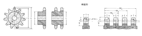 adjustments in response to the elongation of a smoothly rotated roller chain with the lapse of service time, ANSI specify two kinds of tooth profiles: U-type and S-type. In general, S-type tooth profiles are adopted in accordance with ANSI, and our conventional sprockets also have S-tooth profiles.
This gage checks the wear-elongation of chains.
Verify the chain elongation at a portion which can be most
usually engaged with all the sprockets (portion more than likely  to become worn).
When the center with the pin of your chain to become measured
This gage checks the wear-elongation of chains.
Check out the chain elongation at a portion and that is most
frequently engaged together with the sprockets (portion almost certainly to become worn).
When the center in the pin on the chain to be measured reaches the arrow stage, it implies that the chain has become critically elongated. In this case, change the chain.
Make use of the gage to examine the put on elongation of one’s chain.
Standard terms for sprockets
Nominal quantity of sprockets
The nominal amount of a sprocket is definitely the identical because the nominal amount of the corresponding chain. By way of example, Chains such as 50, 50HK, and 50LD might be engaged which has a sprocket 50. It truly is followed by symbols and characters indicating the amount of chain strands, the number of sprocket teeth, hub kind, tooth head hardening, and so forth.
Diameter of ready hole and shaft hole finishing
A regular sprocket for any single strand or double strand chain has a shaft hole ready at a diameter stated within the table of dimensions. If you finish the shaft hole, machine it in reference on the outer diameter or root diameter.
Hardening of tooth heads
The teeth of the sprocket has to be difficult and dress in resistant because they are impacted when engaged with the rollers with the chain and worn by sliding together with the rollers. When severe wear and big shocks are anticipated, sprocket.
Sorts, building and materials
made of carbon steel or cast steel ought to be applied and high-frequency hardening ought to be carried out.
The regular sprockets forty to 120 which has a hub on only one side for single and double strand chains are induction-hardened even when the number of teeth is compact. No matter if the product or service is induction hardened or not is proven during the tables of dimensions of respective sprockets for the reference. In addition, while in the following cases, induction-harden the teeth on the sprocket.?The tiny sprocket has twenty or significantly less teeth and it is utilised at 1/6 or more with the optimum velocity stated during the table of highest kilowatt ratings.
The small sprocket is made use of at a adjust gear ratio of four:1 or extra.
The compact sprocket is utilised for a very low speed massive load transmission as in situations of choice based upon the “Low-speed selection”.
Sprockets are utilized in situations where the teeth are heavily worn.
Sprockets are made use of underneath ailments where there are actually frequent commences and stops or sudden normal or reverse rotations.
Common cautions
For choosing the amount of teeth and pace ration of your sprocket, see “How to select appropriate chain” . For cautions for putting in a sprocket on the shaft and substitute timing, see “Installation adjustment maintenance” .
C-Top is often a plastic cover for chains that may be simply connected. It’s sufficient load strength for chains conveying products. In contrast to traditional plastic chains, it might be utilized underneath substantial tension as stainless steel chains. It is actually an excellent answer for your use that involves the strength of steel chains no cost from considerations of damaging, soiling, and jamming of products. In addition, it prevents operators from currently being caught by the chains. It could possibly also be used since the cover for chains made use of for elevating gadgets this kind of as multilevel parking machines.
Applicable chains
Can be connected to chains corresponding to ANSI #40, 50, 60.
Sprocket teeth quantity
Use sprockets with 12 or additional teeth.
Check the outer diameter on the hub.
Colour
The normal colour for this products is blue gray. Other colors might be supplied dependant upon the amount.
Chain Lube (420 ml)/ HI-PWR Lube (330 ml)
Chain Lube is usually a spray sort lubricant that was produced specifically for chains. It has excellent capabilities that lengthens the chain existence preventing it from wearing and maximizes the chain’s transmission efficiency.
Applications
?Roller Chains for Energy
Transmissions
?O-ring chains
?Leaf chains
?Common conveyor chains ?Motorcycle chains
?Bicycle chains
?Sprockets
Options
?Superior adhesion and less splatter. ?Fantastic lubricity to boost dress in
resistance.
?Great penetration.
?Higher corrosion prevention impact. ?Great water resistance and unlikely
for being washed away by water.
?Fantastic heat resistance.
?Won’t impair the O-rings.
Leaf chains include pins and plates only and therefore are increased in power than roller chains. They’re appropriate for duties like hoisting and pulling. Leaf chains conform to ANSI and also have two types: AL and BL.
AL style
To the use that static load is utilized with little concern of sporting.
BL style
For that use that put on resistance is required given that influence load is applied.
Choice of leaf chains
The chain size is selected according on the following formula:
Acting tension?¨¢Service factor¡§QMaximum allowable tension Notes:
1. Acting tension consists of the dead excess weight from the chain, the fat of the attachments and inertia.
two. In case the chain speed exceeds 30 m/min, use a roller chain.
Minimal sheave diameter: S.D = Chain pitch?¨¢5
Minimum width among flanges: L = All round length of pin?¨¢1.05
?If connecting pins are presented: L¡§R2L1?¨¢1.05
F.D = S.D + Maximum hyperlink plate height (H) Note:?If dimension H exceeds 25.4,
F.D = S.D + 25.four could be adopted since the minimal flange outer diameter.
Periodical inspection and directions for replacement
Make sure you carry out periodical inspection and lubrication to confirm security and prolong chain life. Difficulties and instructions for option are outlined while in the following.
Problem:Circumferential put on of plate
Alternative:Exchange the chain if dress in reduction gets to be five % of H.
Challenge:Oblique dress in of plate and pin head
Remedy:Align the unit.
Issue:Abnormal protrusion or rotation of pin head
Alternative:Exchange the chain Lubricate and eradicate overload.
Trouble:Dress in elongation
Solution:Exchange the chain when its length turns into one.03L. Note: Dress in elongation of the
chain lowers its tensile power.
Wear elongation of 3% lowers the tensile strength by 18 %.
The wear lifestyle of chain could be enhanced by lubrication. Substitute the chain.
Challenge:Cracked plate (one)Crack: From the hole of a link plate towards the finish on the link plate while in the route perpendicular to stress course.
Resolution:Exchange the chain having a chain of greater greatest allowable stress, or lower the load or dynamic (shock) load.
Challenge:Cracked plate (2)Crack: In an oblique route against stress direction.
Resolution:Exchange the chain, and defend from corrosive conditions.
Challenge:Broken plate(by high stress)
Solution:Replace the chain, and eliminate the trigger of overload.
Dilemma:Enlarged plate hole
Alternative:Replace the chain, and eliminate the trigger of overload.
Challenge:Corrosion of pit
Resolution:Replace the chain, and shield from corrosive conditions.
SC silent chains (SCA, SCR, SC)
SC silent chains use specially-coated round pins and distinctive plates to achieve an excellent engagement mechanism, and can preserve a noise degree remarkably decrease than typical roller chains.
SC type silent chains might be utilized for substantial speed and substantial stress transmission just like a toothed metallic belt since the plates directly engage together with the 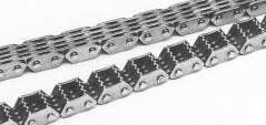 sprockets for driving.
SCR-04 silent chains are intended with inner engaging framework for even more lowered noise level.
PS silent chain
A PS kind silent chain features a structure during which a set of specially formed connecting pins and locker pins get in touch with each and every other even though rotating at every single versatile bearing position. As a result, it generates less heat primarily in substantial pace operation and it is great in sturdiness. On top of that, the specially formed pins greatly lower shock once the chain is engaged with sprockets, offering a higher silencing result than SC silent chains.
Sprockets
Sprockets for silent chains adopt unique modules in involute tooth types to the SCA 04××, SC 25××, SC 06×× within the past web page and PS silent chains to make certain silent substantial velocity operation. For all sizes, the sprocket tooth heads usually are hardened by induction hardening or carburizing.
Due to the incredibly higher technical demands derived through the development on the car business, rapid strides have been created from the growth of engine mechanism chains this kind of as timing chains for driving cam shafts on 4-cycle engines utilized in motorcycles and motor autos, chains for driving oil pumps, generators along with other auxiliary machines, and chains for driving balancer shafts. We’ve got world class technical experience within this spot. The engine mechanism chains have great dress in resistance, fatigue power, silencing effect and shock strength capable of withstanding higher velocity operation, and might meet the ailments required for today’s strong still down-sized substantial performance engines. For silent chains, see the area for silent chains on this catalog.
The values of max. allowable load will not be applied to connecting back links. Do 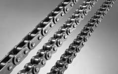 not use connecting hyperlinks in engines.
The smallest chain complying to ANSI is 25 of six.35 mm pitch. Nonetheless, in response to your demands for smaller sized chains in recent years for high technological innovation machinery such as office products, medical machines and industrial robots, we supply 15 of 4.7625 mm (3/16 inch) pitch and also 15H1 being a high-power edition of 15. These high precision chains are produced underneath severe excellent control in particular demanded for tiny sizes, taking wear resistance also into account.
Variety of chain
Refer towards the “Low-speed selection”. Nevertheless, the chain operation velocity can be set significantly large dependant upon the sort of lubrication as proven within the table beneath.
Connecting backlinks and offset back links
R connecting back links are made use of for tiny pitch chains. On the other hand, since their power is decrease than that with the base chain, and because the clip is likely to come off in higher pace operation, the use of connecting hyperlinks is not proposed. Use a loop chain without attaching connecting backlinks.
Offset back links can be found for chains apart from 15 and 15H1, but their use isn’t advised for the very same motive as stated for that R Connecting backlinks.
Operating speed and form of lubrication
15: A high precision mini-pitch bushing chain that’s smaller sized than 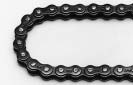 a compact drive chain for basic applications, 25
25: Smallest bushing chain among ANSI normal chains using curl bushings.
35: A ANSI conventional bushing chain appropriate for compact precision machines that call for higher strength.
Responding to different variety of needs
Bicycle Chain
1.Rustproof treated Hi-Guard
(E) obtainable
two. Lightest with the exact same size versions
Tiny Pitch Chain
1.Ultra-precise chain
two. 4.7625 mm pitch available
3. For high-tech machines
Engine Mechanism Chain
1.Camshaft drive timing chain
2.Drive chain of attached units
(oil pumps and so forth)
three.For substantial efficiency engines
Silent Chain
one.Great engaging structure
2.High-speed powerful tensile transmission possible
three.Substantial noise reduction
Silent Chain
one.Greater durability compared
to SC
2.Larger noise reduction compared to SC
Agricultural Roller Chain
1.Extremely dress in resistant
2.Remarkably heavy-load resistant
three.Extremely shock load resistant
BS Roller Chain(ISO  B-series roller chain)
1.Complying with ISO “B series”standard
two.Complying with the British and German Requirements
3.Sprockets comply with all the British Conventional.
Leaf Chain
1.Composed of pins and plates only.
2.Higher strength in comparison with roller chains
3.Two sorts are available: AL and BL.
Furthermore to basic chains, we also manufacture quite a few chains designed for specific applications such as bicycle chains and motorcycle chains.
Some specialty chains might be engaged with typical sprockets. Wear resistant properties of general chains are integrated while in the specifications of each style of specialty chains.
Specialty chains are classified as follows:
?Bicycle Chain
?Compact Pitch Chain
?Engine Mechanism Chain
?Silent Chain
?Agricultural Chain
?Leaf Chain
?BS form Roller Chain (British Regular Roller Chain)
Bicycle Chain
Bicycle chains are emblematic on the DID brand, and we were founded originally for your production of bicycle chains. They’ve got been made use of in lots of bicycles manufactured in Japan and around the world nations.
Just lately, our Hi Guard Chain (E) with an extra rust preventive treatment has favorable track record by customers. The bicycle chains are constantly examined and enhanced in functionality, high quality and specs as noticed in the availability of recent merchandise. As a end result, these are the lightest and most compact chains among goods with the similar dimension. Presently, they may be made use of not just for bicycles but for a lot of functions this kind of since the driving of vending machines and agricultural implements and for conveyor techniques.
Unparalleled noise reduction
Super Very low Noise Chain (UN) has attained a increased drive performance although acquiring equivalent noise reduction functionality to Former Low Noise Chain (TB). By improving the drive functionality to your level of typical roller chains, Low Noise Chains are now applicable to lots of additional machines and gear.
one.Noise reduction equivalent to Preceding Minimal Noise chains
The noise emitted once the chain engages using the sprockets can be decreased by approx. 10dB. For conveyor chains, sliding noise of your rails and the rollers can be decreased too.
two.Durability equivalent to conventional chains
The chains exhibit durability higher than Past Reduced Noise chains and in the similar level as normal chains.
?Typical connecting back links and sprockets may be utilised. Offset hyperlinks are specialized.
?Preventing partial put on of sprockets and rails
Compared to Former Minimal Noise chains, the steel rollers from the Super Minimal Noise are in staggered assembling within the traveling path to cut back partial wear on the sprockets and rails.
Super Minimal Noise Chain (UN)
A fresh lower noise chain with unparalleled noise reduction
Super Low Noise Chain (UN) has accomplished a higher drive effectiveness when having decreased noise like Preceding Low Noise Chain (TB). By strengthening the drive performance for the degree of conventional roller chains, Very low Noise Chains are now applicable to a lot of extra machines and equipment.
Attributes
?Super Low Noise Chain was designed in response to your requires for any wider application of very low noise chains by modifying the triple-layer roller construction in the TB Chain right into a double layer roller. Noise reduction level is equivalent to that of TB Chain.
Advised utilizes
?Conditions requiring the drive effectiveness of
chains with the noise amount of belt conveyors
?Printing machines, packaging machines, office appliances and so on.
Noise reduction comparison
There’s about 10dB noise reduction to the noise from once the chain engages with all the sprockets. (Fig. below) The sliding noise 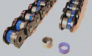 from your rails plus the rollers can be diminished at the same time.
Super very low noise chains are available up to 5 strands.
Sprockets, connecting links and offset hyperlinks
Conventional sprockets and connecting links is often utilized. Offset backlinks are also offered.
It is actually encouraged to use the sprockets with teeth of odd numbers as well as numbers indivisible by four to engage them together with the chain rollers.
Caution
The rollers are made of risen and their overall performance deteriorates when exposed to ultraviolet (UV) rays. In addition, usually do not use in conditions wherever the resin roller are exposed to sprays and vapors of substances listed below:
Nonflammable hydraulic oil (phosphoric esters, water-glycol fluid), oils containing extreme-pressure additives, hot water, vapor, ester, ketone, organohalogen, pure aromatic compounds, powerful acid, sturdy primary agents, powerful acidic reagents, carbon disulfide, sulfur dioxide.
The applicable circumstances are equivalent to people of standard roller chains.
The corrosion resistance against water, acid, alkaline, and also other chemical substances can also be equivalent to that of conventional roller chains.
Chain manufactured of specialized materials
for severe low-temperature down to -40??C.
Common roller chains typically come to be vulnerable to brittle fracture when utilized in temperatures underneath -10??C. We suggest utilizing this chain manufactured of specialized materials with high resistance to cold brittleness when working with chains in extremely lower temperatures. By setting the circumstances in accordance to the beneath table of highest allowable load, the chain might be utilized in temperatures right down to -40??C.
Recommended employs
?Within freezers, conditions of high altitude or cold climates
Choice of chains
The utmost allowable load of Low-temperature Resistant chains vary by temperature. Please refer to the table in the prior webpage for chain variety. Please refer to P120~122 for other criteria. If used in regular temperature, superior shock resistance is usually expected in comparison with regular roller chains.
Connecting back links and offset back links
R connecting back links are applied for Low-temperature Resistance chains #60 or smaller sized and C connecting backlinks for #80 or greater. You will discover no offset links.
Sprockets
Common sprockets might be made use of for Low-temperature Resistance Chain as their dimensions are equivalent to typical roller chains.
Caution
Please use lubrication oil for cold resistance for that upkeep of the chain.
Stainless Steel Chains
together with the capabilities of natural environment resistant and put on resistant chain series.
With the utilization of X-rings, sturdiness 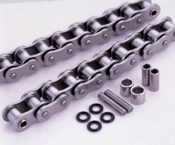 enhanced remarkably.
X rings had been added to the Stainless Steel Chain (SS)
which has the top resistance to corrosion and heat. In comparison with the traditional Stainless Steel Chain,this chain has about 5~10 occasions resistance to abrasion.This improvement helps make feasible a large reduction within the working and upkeep costs.
Advised utilizes
?Problems continuously exposed to chemical agents, sea water and wastewater.
Many chemical plants, water therapy plants
?Conditions of large temperature
Heat-treating furnaces, dry furnaces, incinerators
The grease and seal rings meet the requirements in the Foods Sanitation Law.
Check with us regarding the environmental ailments and chain assortment.
Collection of chains
The typical tensile strength and maximum allowable load on the Stainless Steel Chain are both reduce than a common roller chain. Refer to the highest allowable load for the choice of chains.
Connecting back links
R connecting backlinks are utilised for Stainless Steel Chains #60 or smaller and C connecting back links for #80 or greater.
Sprockets
The pins for the X-Ring chains are longer than individuals of standard roller chains, and thus standard sprockets for multiplex chain can’t be employed to the X-Ring chains when using this chain in multiplex.
Caution
As a common home of stainless steel, anxiety
corrosion cracking and pitting corrosion is usually brought on by chlorine and chlorine ion (CR-).
Please consider into consideration the disorders, temperature, level as well as other overall predicament when working with.
Great resistance to corrosion and heat that permits use in virtually everywhere
You can find two sorts of Stainless Steel Chain: SS and SSK. The SS type has the highest resistance to corrosion and heat. Nonetheless, it is actually made fully of austenite stainless steel and therefore its tensile strength is somewhat decrease than 70% of the standard roller chain, and optimum allowable load drops to a bit in excess of 10%.
By using precipitation hardened stainless steel for your pins, bushes and rollers, the SSK style has 1.5 instances larger highest allowable load in contrast on the SS form. Choose SSK once you want more strength than SS, or want longer merchandise existence.
The two sorts have equivalent corrosion resistance.
Recommended utilizes
?Circumstances exposed to mild alkaline and mild acidic
chemical agents, sea water and wastewater. Many chemical plats and water remedy plants.
?Problems of substantial temperature
Heat-treating furnaces, dry furnaces, incinerators
Collection of chains
Stainless Steel Chain has reduced normal tensile strength and optimum allowable load in contrast for the regular roller chain.
Connecting back links and offset links
R connecting links are applied for Stainless Steel Chains #60 or smaller and C connecting backlinks for #80 or bigger. 2POJ offset backlinks are made use of for sizes #25, and OJ backlinks for all other sizes.
Sprockets
Typical sprockets for Stainless Steel chains might be made use of because the dimensions would be the very same as regular roller chains.
Caution
As a general property of stainless steel, pressure corrosion
cracking and pitting corrosion is usually brought on by chlorine and chlorine ion (CR-).
The chart on right shows the information of exams on the level of corrosion resistance for every medium and does not assure the efficiency from the chains. Please think about the conditions, temperature, level and various overall predicament when employing.
Steel chain approaching stainless steel chain in corrosion resistance
Double Guard Chain is extremely corrosion resistant with coating of double layers of two diverse materials. In comparison with the High-Guard Chain, it exhibits almost doubled corrosion resistance during the salt water spray check, and might be used in mild alkaline and mild acidic problems.
Capabilities
?With its enhanced corrosion resistance, it may possibly be utilized in conditions exactly where High-Guard or Rustless Chains can’t be made use of, and in many cases in some circumstances the place only stainless steel can be applied.
?The coating consists of environmentally pleasant non-chrome material. To comply with all the EU’s Restriction of Hazardous Substances (RoHS) Directive, hexavalent chromium will not be applied.
Recommended makes use of
?Conditions that call for both strength and corrosion resistance
Multilevel parking facility, moving decks, cleansing lines etc. ?Circumstances exposed to rain or sea water
Machines set up outdoors, amusement machines
?Conditions exposed to mild alkaline and mild acidic chemical agents, sea water or wastewater. Various chemical plants and water therapy plants.
Collection of chains
Double Guard 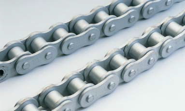 Chain has an equivalent power to a regular roller chain.
Connecting links and offset back links
R connecting back links are employed for high-guard chains #60 or smaller and C connecting hyperlinks for #80 or more substantial, and OJ and 2POJ are applied as offset back links.
Sprockets
Typical sprockets for high-guard chains is usually utilised because the dimensions will be the same as typical roller chains.
Caution
Use stainless steel chains if your chains will can be found in direct speak to with foods.
Double Guard chain isn’t going to have a gloss such as the nickel coated chain.
Unless not so specified by the purchaser, chains are coated with grease and shipped. If doable, oil the spaces between pins and bushes and bushes and rollers. Please utilize the encouraged lubrication oil for the maintenance of your chain as oiling with grease could cause flexion failure.
Extremely protective coating that goes far beyond the functionality of nickel plating
Hi-Guard Chain has increased corrosion resistance upcoming to stainless steel chains. The surface in the chain is finished in non-gloss white hugely protective coating. It’s exceptional resistance to anti-corrostion and rusting. It’s equal strength to regular roller chains, and can be utilized in situations in which strength larger than that of stainless steel chains is required.
Attributes
?Because substantial guard coating acts as being a sacrificial anode for the chain physique, it is possible to count on adequate corrosion resistance even if the coating has come off to some extent.
?The coating consists of environmentally friendly chromium absolutely free materials. To comply using the EU’s Restriction of Hazardous Substances (RoHS) Directive, hexavalent chromium will not be utilised.
Advised makes use of
?Applications call for each power and corrosion resistance
Multilevel parking facility, moving decks, cleansing lines and so on.
?Conditions exposed to rain or sea water
Machines set up outside, amusement machines
Choice of chains
Large Guard Chain has strength equivalent to common roller chain.
Connecting hyperlinks and offset hyperlinks
R connecting back links are utilised for Large Guard Chains #60 or smaller and C connecting back links for #80 or greater. 2POJ offset links might be used for sizes #25 and #35, and OJ and 2POJ for all other sizes.
Sprockets
Regular sprockets for High Guard Chains may be employed due to the fact their dimensions are the same as these of normal roller chains.
Caution
Use stainless steel chains in the event the chains can be found in direct get in touch with with meals.
Substantial Guard Chain doesn’t have a gloss like the plated chain.
High-guard coating has exceptional standard corrosion resistance, but has bad alkaline and acidic resistance.
Except if not so specified through the buyer, chains are coated with grease just before delivery. If attainable, lubricate the spaces in between pins and bushings and bushes and rollers. Please make use of the advised lubricant for that servicing of your chain due to the fact lubrication utilizing grease may cause flexion failure
Specialized nickel plating to get a neat and clean appearance and corrosion resistance
The surface of Rustless Chains is nickel plated for an attractive exterior and corrosion resistance. It’s going to exhibit great corrosion resistance primarily when made use of in blend with grease lubrication. You are able to count on the impact to delay hydrogen brittle destruction when used in conditions the place chains are exposed to sea breeze or acidic sprays.
Features
?The chain is protected even if in use with gilding or alumite machines that emit corrosive steam.
The effectiveness of rust resistance and corrosion resistance with the nickel plating does not deteriorate even underneath problems of substantial temperature and continues to guard the chain.
?The chain’s fine exterior tends to make it suitable for machines for demonstration.
Recommended utilizes
?Whenever a clean look is preferable
Foods sanitation machines, office machines, textile machines, printing machines, pulp processing machines and so on.
?When using within a corrosive natural environment Chemical machines, gilding machines, alumite machines
?Whenever a neat exterior is necessary Demonstration machines at exhibitions and so forth.
Selection of chains
The power of Rustless Chain is equivalent with standard roller chains.
Connecting links and offset links
R connecting hyperlinks are applied for Rustless Chains #60 or smaller sized and C connecting links for #80 or larger. We supply 2POJ offset back links for sizes #25 and #35, and OJ and 2POJ for all other sizes.
Sprockets
Typical sprockets for Rustless Chains may be utilized because the dimensions are the identical as common roller chains.
Caution
Please use stainless steel chains when the chains are to get frequently exposed to water, sea water, liquid remedies or corrosive remedies.
Except if wot so 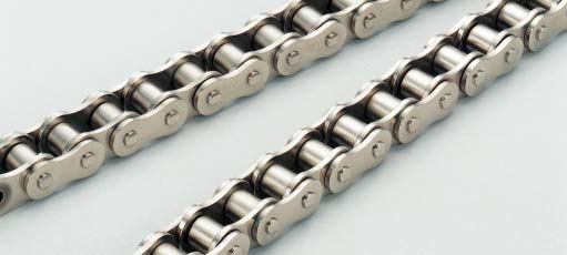 specified through the purchaser, chains are coated with grease in advance of delivery. Please use the encouraged lubricant for that maintenance of your chain considering the fact that lubrication working with grease can cause lubrication failure.
Talk to us in the event the chain is always to be used for hoisting applications.
Maintenance cost-free chains applying sintered alloy bushings
Sintered bushing roller chain is maintenance-free chain ideal to a location where lubrication is difficult. It makes use of bushings made of a sintered alloy which impregnates lubricating oil.
For your use that calls for clean appearance, rustless kind (URN) is available.
Encouraged utilizes
?Conditions the place lubrication is tough or elongation of chain commonly occurs Remarks for use.
?Will not use this chain in dusty environments. In such environments, use O-ring chains.
?This chain is to the use under light or medium load.Use O-ring chain when a large effect is applied to a chain.
?Set the chain feeding velocity at 150m/min. or reduce.
Variety of chains
As for sintered bushing roller chains, the inner plates are thicker along with the pins are longer than individuals of typical roller chains in order 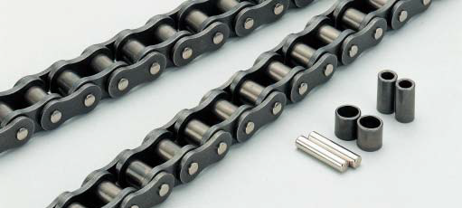 to compensate for your power lowered from the utilization of sintered bushings.
For choosing a suitable chain, refer to “Selection of Chains”. Utilize the tables of highest kilowatt ratings for sintered bushing roller chains that cover reduced velocity ranges.
For sintered bushing roller chains, “Low-speed selection” are unable to be made use of because the “Maximum allowable load” inside the dimension table considers only the chain tensile stress and neglects the bushing power.
Connecting backlinks and offset backlinks
For sintered bushing roller chain, R connecting links are utilized for DID60 or smaller, and C connecting back links for DID80 or larger.
OJ may be employed as offset backlinks. Please spot an purchase the connecting back links and offset links specifying the type for sintered bushing roller chain.
From the tables of optimum kilowatt ratings, the strength of your connecting hyperlinks and offset hyperlinks are taken under consideration.
Sprockets
Typical sprockets could be utilised for sintered bushing roller chains.
Highest put on resistance available by sealing grease concerning pins and bushings
The sturdiness of chain is radically improved due to the fact grease is sealed amongst the pins and bushings by O-rings. The O-ring chain could be the most dependable model of your Greatest Daily life Chain Series with its fantastic wear resistance even during the situations or environments wherever chain upkeep is tough.
Recommended employs.
?Circumstances where regular chain replacement is required due to wear stretch
?Conditions in which lubrication during the services is unattainable
?In an environment with considerably soil, sand, dust, and so forth.
?Applications that demand power greater than that of a sintered bushing roller chain
Other features
?Cutting down noise. (The noise level is 3 dB reduced compared to common roller chains.)
?Minimizing vibration with all the friction designed by O-Ring. (The electrical power loss because of the friction is nearly negligible, because the frictional force concerning the pins and bushings is for ordinarily inside the applications.)
Collection of chains
The strength of an O-ring chain is almost  the exact same as that of the common roller chain. (Since the pins are longer than these of regular roller chain, the average rupture strength is slightly decrease.)
For selecting an appropriate chain, refer to “Selection of Chains” .
Once the support ambient temperature is higher than 80° C, unique heat resistant O-rings has to be utilized. In this instance, get hold of us for additional data.
Connecting links and offset links
Two forms of connecting links are available: clearance match and interference match. When high strength or durability is needed, use interference-fit connecting hyperlink. Only 2POJ is obtainable since the offset link for all sizes.
Sprockets
O-ring chain employs longer pins than a regular roller chain. When using multiplex O-ring chain, the standard sprocket for multiplex chains can’t be used.
Caution
O-ring chain just isn’t suggested in applications in which solvents or other substances may possibly assault “Nitric Rubber”. Particular materials O-rings may also be offered for these disorders: Please consult us for specifics. Usually, “Nitric Rubber” is broken by get hold of using the following chemical materials.
The pin which has a super-hard
surface coating
protects the important place
from 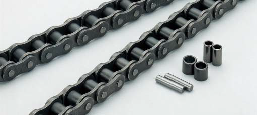 adverse environments
Great lubrication can make chain existence longer. It really is not effortless to avoid deterioration resulting from its personal oxidation and mixture with contaminants. In this instance, DH-αchain demonstrates fantastic functionality. Excellent functionality may be anticipated underneath non-lubricated ailments and in such significant ailments wherever dirt, dust or fine metal particles do the job to the chain.
Advisable utilizes
?Environments wherever soil, sand or dust straight comes
into make contact with together with the chain (O-ring chains are advised if applicable.).
?Applications the place a chain is lubricated in an oil bath along with the oil is heavily deteriorated on account of the contamination of foreign objects.
?To avoid chain kinking by heat concerning pin and bushing
Assortment of chains
The power of DH-αchain is the same as that of normal roller chains. For picking out a suitable DH-α chain, refer to “Selection of Chains” .
Connecting hyperlinks and offset hyperlinks
Make use of the connecting backlinks and offset back links for normal roller chains. Although a chain has a lot of back links, the numbers of connecting hyperlink and offset link is one or two, and, consequently, their influence about the put on from the total chain is small.
Sprockets
The dimensions of DH-αchain is the same as those of conventional roller chains. Use typical sprockets for conventional roller chains.
Seamless High-precision Solid Bushings Stop Chain Elongation
Solid Bushing chain is highly wear-resistant applying cold formed reliable bushings using a seamless smooth surface and total roundness.
This is actually the popular sort amid the Ultimate Life Chain Series with its enhanced grease retention concerning the bushing as well as pin.
The solid bushings and our patented V grease lengthen the dress in life from up to four instances compared to conventional roller chains. We recommend you to adopt this reliable bushing chain if you’re wishing to cut back the frequency of upkeep.
Advised uses
?For strengthening wear resistance while retaining the merits of conventional roller chains.
?For Circumstances exactly where chain elongation occurs frequently or lubrication is tricky.
¡êaWear resistance is often additional enhanced when DH-|¨¢ coating pins are employed.
Collection of chains
The strength of the solid bushing chain could be the same as that of regular roller chains. For selecting an appropriate chain, refer to “Selection of Chains”.
Connecting back links and offset links
R connecting links are utilised for DID 60 or smaller chains, and C connecting hyperlinks are utilised for DID 80 or greater chains. As for offset back links, 2POJ is used for DID 25 and DID 35, and both OJ and 2POJ might be utilised for greater sizes. Regular offset back links could be applied.
Sprockets
The dimensions from the strong bushing chain will be the similar as people in the regular roller chain. The regular sprocket may be employed.
High-end style of the high strength series
The DID HI-PWR-SHK roller chains have thicker hyperlink plates than HI-PWR-S roller chains, and therefore are the highest in tensile strength and allowable load among common application chains, consequently being appropriate for reduced speed hefty duty transmission.
Proposed employs
?The HI-PWR-SHK roller chains are 25 % 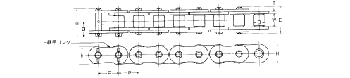 increased in tensile power and 50 % larger in optimum allowable load compared to the common roller chains, but due to the fact their fat is heavier, driving effectiveness declines at substantial speed. So, they can be appropriate for heavy duty at lower velocity applications.
Multilevel parking machines, pipe benders, construction machines, and so forth.
Variety of chains
Select a correct HI-PWR-SHK form chain dependant on “Low-speed selection”
HI-PWR-SHK series is obtainable in simplex.
Sprockets
Normal sprockets for multiplex chains are unable to be employed.
Connecting hyperlinks and offset back links
The top attribute on the HI-PWR-SHK roller chains is large maximum allowable load. Thus, interference-fitted connecting back links (H connecting back links) with little strength degradation are utilised.
The connecting plate as well as connecting pins are connected with spring pins. The tensile strength of an H connecting link is equivalent to that in the chain, however the allowable load is somewhat reduce than that from the chain.
HI-PWR-S sort roller chains don’t have any offset website link. Use an even quantity of hyperlinks.
Hardly ever make the holes in the connecting plate bigger and never ever make the pins thinner to facilitate the perform for fitting the pins into the connecting plate, because otherwise the fatigue strength will probably be lowered.
Downsizing Your Technique with Greater Power Chains
HK form roller chains conform to H style of ANSI, and their thickness of inner and outer link plates are equal to people of your next bigger dimension chain. Hence, HK form roller chains are greater in tensile power by about 20%and in optimum allowable load by about 15% than these of conventional roller chains. Because the fat on the chains is additionally larger, HK form roller chains are ideal for that application of heavy duty at low pace.
Proposed utilizes
?Optimal for locations in which increased strength is required but big and heavier chains can not be made use of.
Variety of chains
Choose a appropriate HK type roller chain depending on “Low-speed selection”
For your highest allowable load, see the following table of dimensions.
HK type roller chains are available up to triplex.
Sprockets
Use regular sprockets for a simplex HK roller chain Because the transverse pitches are more substantial than those of common chains during the situation of duplex or triplex, standard sprockets can’t be utilized. Refer to the sprocket tooth profiles for HK
Connecting hyperlink and offset website link
The tensile power of connecting hyperlinks and offset links are listed on the left, however the maximum allowable load is lower than that in the base chain. Please seek the advice of us should you’ve 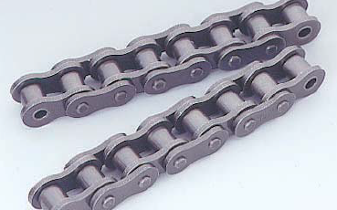 any inquiries. It can be suggested to utilize the connecting website link of interference-fitted (FJ, HJ)
By no means make the holes on the connecting plate larger and under no circumstances make the pins thinner to facilitate the work for fitting the pins in to the connecting plate, since otherwise the fatigue strength will be lowered.
Choice of chains
Select a suitable HK kind roller chain determined by “Low-speed selection”
To the highest allowable load, see the next table of dimensions.
HK type roller chains are available as much as triplex.
Sprockets
Use common sprockets for any simplex HK roller chain Since the transverse pitches are larger than individuals of typical chains within the case of duplex or triplex, typical sprockets are unable to be applied. Refer towards the sprocket tooth profiles for HK
Connecting link and offset link
The tensile strength of connecting hyperlinks and offset links are listed around the left, but the highest allowable load is lower than that of the base chain. Please seek advice from us ought to you’ve any questions. It truly is suggested to work with the connecting website link of interference-fitted (FJ, HJ)
In no way make the holes from the connecting plate greater and in no way make the pins thinner to facilitate the function for fitting the pins in to the connecting plate, due to the fact otherwise the fatigue strength will likely be lowered.
Substantial power roller chains with enhanced fatigue strength and affect power
HI-PWR-S roller chains are enhanced in fatigue strength and effect power without having modifying the dimension within the pin length direction of regular roller chains. Plates are enlarged, as well as machining accuracy and assembling accuracy of components are improved. The roller chains hold higher transmission efficiency for applications from minimal to large speeds and are impressive enough to withstand long-term use.
Encouraged utilizes
?Compared to typical roller chains, HI-PWR-S roller chains are greater in optimum kilowatt rating by about thirty % inside a medium to minimal speed range. They exhibit exceptional capability in places wherever massive shock loads are applied, drive units for regular start/stop, and also in higher velocity applications.
?Civil engineering machines such as skid steer, trenchers, trucks, cranes, agitating trucks, forklifts and drive units for conveyors, elevators, stackers, and so on.
Choice of chains
On the whole, pick your chain with reference to “Designing of Chain Transmission” and also for the tables of “Drive Performance” and “Dimensions” of HI-PWR-S type roller chains.Having said that, only for any special case of lower speed and significantly less shock, “Low-speed selection” is also applicable.
Sprockets
HI-PWR-S Roller chains and ANSI normal chains would be the similar in essential dimensions. Use ANSI common sprockets.
Connecting back links and offset links
Use H connecting links for HI-PWR-S. In an H connecting link, the pins are lightly interference-fitted with all the connecting plate. For that connection involving the connecting plate plus the connecting pins, spring pins are made use of as opposed to cotter pins to get a common roller chain.
The center plates of an H connecting link for multiplex chain has bushings pressed in.
HI-PWR-S roller chains usually do not have any offset hyperlink. Use an even variety of back links.
Hardly ever make the holes with the connecting plate larger and in no way make the pins thinner to facilitate the function for fitting the pins into the connecting plate, due to the fact otherwise the fatigue power will be 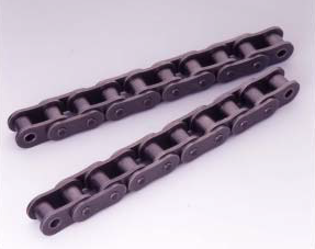 lowered.
The 14 sizes of regular roller chains can be found ranging from 25 to 240 like people in conformity with ANSI (American National Common Institute), and ISO (Global Organization for Standardization).
The chains not only meet the prerequisites for your minimum tensile strength prescribed by ANSI and ISO, however they also supply the leading class quality within the planet such as a high fatigue strength
Appropriate utilizes
?Common use for driving and lifting products.
Examples
?Driving transfer units as well as other products. For multilevel parking.
Collection of chains
For collection of a chain, see the tables of “Max. Horsepower Ratings” for regular roller chains and “Designing of Chain Transmission”. On the other hand, only to get a particular situation 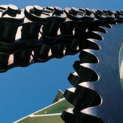 of very low pace and much less shock, “Low-speed selection” technique could also be referred to.
Normal roller chains as much as five strands are available. The standard approach for connecting pins and plates is rivet type (RP).
The cotter kind (CP) is obtainable for normal chains and HK chains of 80 or TRANSFER CHAIN bigger.
Sprockets
The regular roller chains is often engaged with common sprockets of the corresponding nominal numbers. For sprockets, refer for the table of “Dimensions” for every size of chain.
Connecting back links and offset links
For connecting hyperlinks and offset backlinks, refer to your table of “Dimensions” for every size of chain.
The connecting hyperlinks are usually R or C connecting back links in which the pins are clearance-fitted using the connecting plate. Considering the fact that clearance-fitted links are inferior to the base chain in Max. allowable stress as while in the situation of one-pitch offset backlinks (OJ), “Low-speed selection” can’t be referred to. Because the Max. kilowatt ratings are made the decision thinking about the power of connecting links and OJ, the clearance-fitted connecting hyperlinks and OJ may be utilised if your chains are picked in accordance to the “General selection”. When a higher Max. allowable stress is needed to the connecting link, make use of the interference-fitted connecting hyperlink (H connecting website link) of a HI-PWR-S chain, and while in the situation of offset backlinks, use 2POJ.
A roller chain features a construction as illustrated beneath, as well as the names on the parts are stated inside the drawing. These elements act as described under, and therefore are made to suit the respective actions.
Pins assistance the many load acting within the chain, together with inner and outer plates, and when the chain is engaged that has a sprocket, the pins slide as bearings. They may be demanded for being higher in shearing power and bending power, and particularly put on resistance.
Bushings act to stop the shock obtained as a result of rollers when the chain is engaged having a sprocket from remaining directly transmitted to pins, and in addition act as bearings, together with the pins. So, they can be demanded for being large in shock fatigue strength and dress in resistance.
Rollers act to smoothly bend the chain once the chain is engaged having a sprocket, to safeguard the chain from shock with the sprocket. They’re required to become large in shock fatigue power, collapse strength and wear resistance.
Plates are subject to repeated stress in the chain, and in some cases a sizable shock. So, they are really required to become large in tensile strength, and in addition in shock resistance and fatigue power.
Connecting back links
The next 4 sorts of connecting backlinks can be found (R, F,  C and H).
Clip kind connecting website link by which the connecting pins are clearance-fitted together with the connecting plate is termed an R connecting website link (RJ), and that, interference-fitted, is termed an F connecting link (FJ).
A cotter form connecting hyperlink in which the connecting pins are clearance-fitted with the connecting plate is termed a C connecting link (CJ), and that, interference-fitted, is termed an H connecting website link (HJ).
In a regular spring pin style connecting website link, the connecting pins are interference-fitted with all the connecting plates (H connecting hyperlink).
Offset website link
An offset hyperlink is utilised for expanding or reducing the length of the chain by a single pitch, plus the following two kinds are frequently out there.
Because the “connecting link” and “offset link” are lower than the base chain in power, talk to us when making use of them for just about any services affliction in extra of the Max. kilowatt ratings.
*Clearance fit
Within this match, a clearance is normally formed involving the pin and also the hole after they are assembled. This process is used in typical connecting backlinks.
*Interference fit
In this fit, an interference usually occurs when the pin as well as hole are assembled. This process is adopted in base chains and H connecting back links. Even so, in H connecting back links, the interference is smaller sized than that of the chain body.
The countless push to raise sawmill productivity consistently demands larger speed, greater accuracy and much less waste. Chains can perform a function in the mill?¡¥s profitability 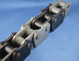 by carrying out superior and lasting longer.
We start with superior layout. We determine the precise degree of tip sharpness to function most effective for each application, creating maximum grip with minimum penetration and tear out. The outcome can be a chain that runs accurately at speeds of in excess of 1,400 FPM.
Superior style demands superior material and fabrication. Chains items are manufactured from major grade material to provide the greater hardness necessary to resist corrosion and oxidation even though keeping power at high temperatures. Chains offers precision ground flat bottom chains that reduces wear and damage for your chain bed and distributes load evenly. Our chains are fine blanked with very low draft tooth profile that distributes weight and minimizes losses from bruising. We manufacture
Chains together with the closest probable tolerances within the industry and offer a one of a kind strong center plate style and design that all but eliminates breakage from sawdust packing.
ISG/IRG/ISW/ISGB/IHG/YG Pipeline centrifugal pump
1.IRG,ISW horizontal and vertical clear water pump is utilized to deliver clear water together with other liquid whose bodily and chemical characters are equivalent to clear water, and is ideal for industrial 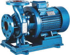 and municipal water provide and sewerage, boosting water supply of high-rise constructing, garden irrigation, boosting for fire fighting, long-distance delivery, heating and ventilating refrigeration circulation.
2.IRG,ISW horizontal and vertical hot water pump is suitable for: metallurgy, chemiacl market, weaving, paper generating.
3.IRG,ISW horizontal and vertical chemical pump is used to deliver liquid which can be without having reliable particles, corrosive and comparable to water in viscosity.
four.ISGB vertical pipe centrifugal pump is usually a type of item that has new construction and innovative technological innovation, and it is researched over the basis of ISG-type pump.
five.ISGB vertical pipe centrifugal pump delivers clear water along with other liquid whose bodily and chemical characters are similar to clear water.(lf the media delivered is with particles, it needs to be described when ordering so as to assemble wearing mechanic seal).
six.IHG-type vertical pipe chemical pump is applied to supply liquid that’s without strong particles, has corrosion and stronger viscosity than water. It is actually appropriate for this kind of departments as petroleum, chemical industry, metallurgy, electrical electrical power, paper manufacture, foods and pharmacy, synthetic fiber. Its operation temperature is in between -20’C and 120’C.
slow rotary velocity centrifugal pump
ISWD. ISGD slow rotary velocity vertical centrifugal pump matches slow rotary velocity motor about the basis of ISGD-type vertical centrifugal pump, notably lowers the working noise, prolongs lifestyle span of conveniently damaged parts. It can be primarily utilized to freezing water, cooling water circulation of air-conditioning, terminal boosting, regional or terminal boosting circulation of municipal heating technique, local consistent voltage of city constructive fire-fighting process, and setting of forms of air-conditioning hot-water boiler.
The series no-jam dredge pump is made through intro ducing overseas productive vitality conservation no-jam dredge pump engineering and organizing the technological electrical power. Its trart parameters all attain or exceed the technological normal with the samekind item in the home and abroad. It introduces distinctive single-channel impeller, and movement seal can be a tricky alloy mechanic seal fitting produced of two groups of unique components, motor is separated with oil chamber, it can be no?1am, wearies effectively, having correct model line, easy to utD?ze and maintain, has large efficiency¡ê?saves power notably, will be the newest products of the same kind in our country, and it is deeply welcomed by its consumers. Several designs and diverse stricture kinds of your pump can be chosen.
The series no-jam dredge pump is ideal for delivering industrial and municipal sewage. Its beat characteris that it could provide sewage with sound particles and fibre materials. In addition to delivering sewage, additionally it is ideal for 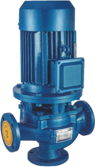 dredge pump, pulp pump, 1?£¤rating washing condensat?¡ê??ycle pump, pump for irrigation and so on. It is actually broadly applied to such events as mining, construction web page, hospital, hotel, sewage remedy.
SPROCKET Functions
PLATE CENTER SPROCKETS
Sprockets are furnished in two primary styles . . . Plate center and Spoked Arm. Plate centers are generally used on smaller sprockets whose dimension prohibits using spoked arms and on drives and conveyors which are subjected to frequent shock loads. They are really also used when the highest allowable chain pull is higher than that which Spoked Arm Sprockets
can stand up to.
SPOKED ARM SPROCKETS
Spoked arms are uncovered on significant diameter sprockets. They are really made use of to cut back fat and facilitate managing.Lightening holes may also be utilized to cut back fat.
CHILLED RIM DISHED AND
FABRICATED DISHED
When producing cast prockets, we use a distinctive chemistry of gray iron that enhances the means with the from the iron to kind a tough “chilled” layer within the rim of the sprocket. All sprockets certainly are a typical class thirty gray iron. This applies to all parts of the sprocket which are not chilled this kind of since the hub and net regions. Surfaces have a minimum brinell hardness of 400 above the entire tooth professional?le.
Fabricated dished sprockets are made to purchase. Products and hard-ness are customized for your prerequisites.
CHAIN SAVER SPROCKETS
Chain 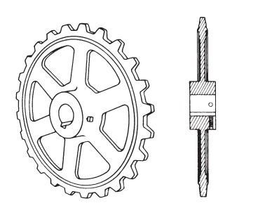 Saver sprockets give extra life to chain because on the unique ?ange building about the rim. The chain side bars rest within the ?ange as chain wraps all over the sprocket, keeping the chain on the correct pitch line and distributing put on above a greater speak to region.
HUNTING TOOTH SPROCKETS
Hunting Tooth Sprockets final longer than ordinary sprockets and operate on this principle: Hunting Tooth Sprockets have an odd number of teeth and are half the pitch with the chain. So, each and every time the sprocket tends to make a revolution, the chain links engage a new set of teeth, forward from the previously engaged set. Every tooth can make get hold of together with the chain only half as a lot of times since it would on a reg-ular sprocket, therefore doubling the life of the sprocket.
SEGMENTAL RIM SPROCKETS
Segmental Rim Sprockets are made to eliminate expensive shut down time in the course of installation and adjustment. They consist of a re-movable segmented rim plus a strong or split body which are bolted with each other. To obtain additional wear from this form sprocket, following con-siderable use, the rim sections may well be simply just reversed, so that the chain can make get in touch with together with the opposite sides of the teeth. Bodies or complete sprockets might be replaced with out removing shaft or bear-ings, producing this kind of sprocket pretty desirable economically be-cause from the cost savings in labor and shut-down time.
Broad FLANGE SPROCKETS
These Sprockets are utilized in many industries such because the lumber and paper industries as sprockets for that delivery finish of conveyors. The broad ?ange or side extension acts as a guard and helps hold materials from becoming wasted since it comes off the end of your conveyor.
TRACTION WHEELS
Traction wheels can be found inside a broad assortment of sizes and varieties to ?t most chains. They can be furnished inside a plate-center style with op-tional lightening holes if needed. Traction wheels is usually either solid, split or segmented building.
Rugged building Type “MD” Buckets are most preferred for standard function elevators. Covering a wide choice of sizes from 4 to 20 inches long, they are really utilized for ?ne and medium size products such as coal, cement, pulp, grain, ear corn, 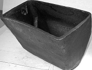 and so on. They are broadly applied for heavy abrasive materials such as sand, gravel, and stone. Reinforced front lips give Design “MD” Buckets an extended sporting digging edge. Uniform wall thickness and solid corner reinforcement make them more powerful than steel buckets with the exact same gauge.They are smoothly surfaced and also have ends sloped inward at six degree angles to insure correct ?lling and clean discharge. Available in Malleable and Al-lied-Locke Promal.
Chain for which buckets can be found in-clude: Steel Bushed Roller, Steel Bushed, Combination, “H” Class Mill, 400 Class Pin-tle, and 700 Class Pintle. “MD” Buckets are employed with G1, G6, K1, or K2 design attach-ments after they can be found from the chain type.
Capacities are for buckets ?lled for the line XX (see diagram). The sensible working capability will fluctuate using the loading problems, angle of re-pose of the material staying dealt with, as well as the incli-nation of the elevator.
Style “AC” ELEVATOR BUCKETS for handling cement, lime, and ?uffy supplies
Fashion “AC” Buckets provide speedy, thorough discharge of cement, lime, and other dry, ?uffy resources. Vent holes during the bottom of every bucket release trapped air in ?lling and allow material to empty from bucket rapidly and completely on discharge. Moreover to reinforcing lips, hooded backs reinforce “AC” Type Buckets. This attribute permits closer bucket spacing and gives 30% greater carrying capacity than other bucket types of the same length. These sturdy buckets have an extra thickness of metal at put on points for longer service. Available in Al-lied-Locke Malleable and Promal.
Type “AC” Buckets are often applied with hefty duty engineering chain such as Bushed Steel Chain with K2 and K3 type attachments.
Capacities are for buckets ?lled to either line XX or YY (see diagram). The useful operat-ing capacity will differ with loading conditions, angle of repose from the material currently being handled, as well as inclination from the elevator.
Elevator Buckets are offered in Styles ?¡ãMD?¡À Mill Duty and ?¡ãAC?¡À Extra Capability.The ?¡ãMD?¡À Mill Duty Bucket replaces former Variations ?¡ãAA?¡À and ?¡ãAARB.?¡À
Design ?¡ãMD?¡À ELEVATOR BUCKETS
Fashion ?¡ãMD?¡À Elevator Buckets will be the most popular buckets for common function elevators. They cover a wide selection of sizes from four to twenty inches in length and are made use of for ?ne and medium dimension materi-als, such as  coal, cement, pulp, grain, and ear corn. They can be also extensively used for hefty abrasive materi-als such as sand, gravel, and stone. Reinforced front lips give buckets a long-wearing digging edge. Bucket walls have uniform thickness and solid corner rein-forcements. Talk to our speci?cation tables for com-plete details.
Out there in Malleable and
Promal or in Fabricated Steel.
Style ?¡ãAC?¡À ELEVATOR BUCKETS
Style ?¡ãAC?¡À Elevator Buckets are added ca-pacity buckets which supply rapid, total discharge of cement, lime, together with other dry resources.Vent holes inside the bottom of every bucket release trapped air on ?ll-ing and allow material to empty from bucket promptly and entirely.The lips are reinforced along with the backs are hooded. These features allow closer bucket spacing and give 30% higher carrying capacity than other bucket types with the similar length. Buckets have further thickness of metal at wear points. Seek advice from our speci?cation tables for full data.
Out there in Malleable and
Promal or in Fabricated Steel.
extended pitch 700 Class Pintle Chain of-fers greatest power at minimal fat. It’s to-tally suited for sewage plant applications too as other conveying and elevating makes use of. Sidebars have casted lugs to ?t.
T-head pins ?t snugly, eliminating pin rotation and stopping the entrance of grime and grit to the accu-rately cored pin holes. Closed bearing development also aids to help keep the chain safe from pitch elonga-tion as a result of abrasive wear.
Riveted chain development is advisable for sewage application, but both cottered or riveted con-struction is available on request. Stainless steel cot-ters might be furnished when speci?ed.
“F” attachments 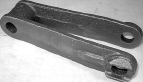 proven during the following pages and tables conform to field requirements. On the other hand, numerous specials are also out there. Contact for particulars.
700 Class Pintle Chain is furnished with carbon steel heat taken care of pins. These pins achieve optimum articulation given that they are man-ufactured to exact diameters which appropriately ?t the ac-curately cored holes of the chain backlinks.
Brutaloy sprocket wheels can be found.The curved sidebars on 700 Class Pintle Chain certainly are a feature which enhances highest chain life when chain is run on Chain Saver Hunting Tooth Sprockets. A, F, K, and M Type attachments are available. The “F” style attachments have large face plates with bolt holes for safe mounting of wooden ?ights.
As drive chain, 700 Class Pintle back links are designed to travel in the path of their barrel ends; as ele-vator and conveyor chain, they really should travel while in the di-rection of their open ends. All 700 Class Chain is made to manufacturer’s standards and it is in-terchangeable with other manufacturers’ chain.
400 Class Pintle Chain is a light-weight, moderately priced chain capable of han-dling common loads at slow or intermediate speeds. It truly is proportionately cast for stability, strength and extended, ef?cient services, and it is out there in riveted or cottered construction. The head of every pin is notched to ?t the sidebar locking lug which keeps the pin from rotating when the chain is in use. Closed bearing building helps make 400 Class Pin-tle Chain helpful in conveying moderately gritty and abrasive  products.
Produced in Promal, having a ten-sile power vary from 7,800 to 28,600 pounds, 400 Class Pintle Chain is thoroughly cored for pitch accuracy with smooth bearing sur-faces that reduce ?¡ãbreak-in?¡À put on leading to pitch elongation.
400 Class Pintle Chain is available inside a pitch array of 1.375 to 3.075 inches with a full as-sortment of cast iron or fabricated steel steel sprockets.
A considerable assortment of attachments are available to take care of a wide wide range of applications. Designs A and G attachments are made available in proper and left hand links.
As being a drive chain, 400 Class Pintle is made to travel within the route of your barrel end from the hyperlinks; as an elevating or conveying chain, its route of travel need to be towards the open ends in the hyperlinks.
All 400 Class Pintle Chain is manu-factured according to manufacturer?¡¥s standards and it is absolutely interchangeable with other manufac-turers?¡¥ chain.
A1 ATTACHMENT
NOTE: ?¡ãR?¡À and ?¡ãL?¡À suf?xes in Attachment Letters designate appropriate hand and left hand attachments.
A12 ATTACHMENT
NOTE: ?¡ãR?¡À and ?¡ãL?¡À suf?xes in Attachment Letters designate right hand and left hand attachments.
TRANSFER CHAIN
is obtainable in ![]() two kinds: “H” Class Transfer Chain and Combination Transfer Chain. “H” Class Transfer Chain in-cludes individuals numbered H 78A, H 78B, H 130, H 131, and H 138. All “H” Class Transfer Chain is obtainable only in riv-eted construction. “H” Class Transfer Chain numbered H 78A, H 130, and H 131 is created with peaked roofs. Chain numbered H 138 and H 78B has ?at roofs.
two kinds: “H” Class Transfer Chain and Combination Transfer Chain. “H” Class Transfer Chain in-cludes individuals numbered H 78A, H 78B, H 130, H 131, and H 138. All “H” Class Transfer Chain is obtainable only in riv-eted construction. “H” Class Transfer Chain numbered H 78A, H 130, and H 131 is created with peaked roofs. Chain numbered H 138 and H 78B has ?at roofs.
Blend Transfer Chain incorporates individuals numbered C55A, C55B, and C55C. It really is offered only in riveted con-struction with peaked roofs.
Each sorts of Transfer Chain, referred to sometimes as “roof top” and “camelback” chain, are de-signed to carry heavily concentrated loads such as lum-ber, boxes, barrels, and crates.They’re generally meant for operation in troughs in two or more parallel strands, with only the tops of the hyperlinks protruding.
All Transfer Chain is accessible in Promal. The tensile strengths of Transfer Chain vary from 11,700 to 29,900 lbs.
Rivet pins furnished with “H” Class Trans-fer Chain are T-head pins which engage two head hold-ers, cast around the side bars of each website link, to stop pin rotation and reduce dress in and elongation of pitch.
Transfer Chain is accessible inside a pitch variety of one.631 to 4.000 inches. Each and every Transfer Chain is manufactured according to manufacturer’s stan-dards and may possibly be interchanged with chain of other man-ufacturers, the place available.
Cast Iron and Fabricated Steel sprockets can be found for each pitch dimension.
“H” Class Mill Chain is an ex-tremely robust, serviceable chain initially de-signed for heavy drives and transfer conveyor functions in saw mills and also the paper and pulp market. “H” Class Chain has confirmed itself for innumerable other industrial applications at the same time, especially for moderate duty in abrasive atmospheres in which hefty, rugged chain is re-quired.
The sidebars from the “H” Class hyperlinks are rein-forced with sporting sneakers which strengthen and stiffen the backlinks when it’s operated in troughs or over ?oors and runways.
Pin holes are precision cored to assure accu-rate pitch sizes, which range from 2.308 to 4.000 inches. “H” Class Chain is obtainable in both riveted and cottered construction. T-head pins engage two lugs cast about the links’ side-bars. This con?guration prohibits pin rotation during chain operation, eliminating abrasive put on and pitch elongation.
“H” Class Chain conforms to manufacturer’s standards and is completely interchangeable with chains of other companies. “H” Class Chain is available in -Locke Promal with tensile ranges of 9,450 to forty,500 lbs.
“H” Class Chain 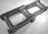 could operate in two directions. Like a drive chain, it travels within the direction in the closed barrel; for elevator or conveyor applications, it need to travel toward the open ends from the links.
Brutaloy or cast steel sprockets are available to accommodate each and every “H” Class pitch dimension. A broad assortment of attachments is additionally avail-able for varied chain applications.
Mixture Chain is applied extensively while in the cement, paper and pulp, quarrying, and mining industries for elevating and conveying a wide wide variety of abrasive and non-abrasive products. It’s also ?nding a lot of utilizes in general in-dustrial assembly conveyors. It truly is not recommended for drive chain.
The construction of Mixture Chain may be both cottered or riveted. Cottered is usually consid-ered regular. Pins have ?at parts at their ends, which lock in to the appropriately punched sidebars, stopping pin ro-tation in the course of chain operation. All pin holes are clean-cored for smooth bearing surfaces and therefore are dimensioned for right pin clearance. Industry dimensional requirements are rigidly maintained and this chain may be interchanged with links of other manufacturers.
Pitch sizes range from 1.631 to six.050 inches; tensile strength range extends from 12,150 to 67,500 pounds. All Mixture block back links except C55 and C55L have elliptical barrels. This adds additional metal the place the sprocket to chain get hold of leads to most chain wear.
MBP 132C has chambered barrels containing grease which lubricates pins, helps to prevent joint freezing, and pro-hibits entry of corrosive and abrasive materials to the bar-rel core.
Attachments can be found in lots of on the pitch sizes to get a broad selection of applications.
Mixture hyperlinks are symmetrical and may well thus be operated in both route of travel.
Brutaloy and cast steel sprockets are available for each pitch size.
COUPLER Links FOR Blend CHAIN
Coupler backlinks are required for joining chain the place no take-up is obtainable. Each chain pitch size features a Promal cast off-set sidebar coupler website link offered for this objective.
Rivetless Drop Forged Chain is highly thought to be one among the strongest chains ever formulated, and has located widespread application in many industries. Since supplies never are inclined to pack in its open struc-ture, Rivetless Drop Forged Chain is  utilised extensively for ?ight conveyors. Its design permits each horizontal and vertical operation above irregular routes, building it particularly adapt-able for trolley conveyor services.
Exclusive characteristics of this chain in-clude optimum power with out ex-cessive weight, and resistance to lengthening even immediately after substantial op-eration.
EGULAR Form
Typical Variety is furnished with only the T-head pins heat treated. These pins are symmetrical and may possibly be reversed when worn.
X-Type is furnished with all parts heat taken care of, and is built to have improved ?exibility, trans-verse power, and much better operating performance.
S-Type is furnished with all components heat handled.
VAILABLE IN 3 TYPES-
Normal Type
Normal Form is furnished with only the T-head pins heat handled. These pins are symmetrical and might be reversed when worn.
X-TYPE
X-Type is furnished with all components heat taken care of, and is made to have improved ?exibility, trans-verse strength, and improved operating performance.
S-TYPE
Barloop chain is manufactured with a common rivet-less block website link and fabricated steel sidebars. Barloop chains give the advantage of the ?at steel sidebar for welding attachments. The pins certainly are a riveted type to keep the sidebars locked, eliminating the possibility of chain coming apart when slack is current and
minimizing put on in between the pin and sidebar.
Engineering Class Drive Chain is intended for power drives, building machinery and conveyors. It operates under the most serious circumstances at moderately large speeds. It’s developed according to ANSI or manufacturer’s requirements. It might be interchanged with common chains of other suppliers, depending on the size. You can find 4 primary styles.
Style one
Typical offset style consists of a roller, bushing, pin and conventional offset sidebars
Style two
Particular developed offset sidebars have a roller, bushing, pin and offset sidebars which are specially formed to optimize articulation exactly where
Style 3
Steel bushed offset sidebar chain features a bushing, pin and offset sidebars. It doesn’t have a roller
Style four
Straight sidebar drive chain has a roller, bushing, pin and straight sidebars
MXS along with other drive chain is available with pitch at this time ranging from 1.500” to seven.000”. Regular ultimate strength ranges from twenty,000 to 600,000 pounds and operating loads can be found from two,300 to 30,600 pounds. Drive chains are available in cottered construction only. the pins are press fitted in to 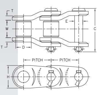 the sidebars, avoiding pin rotation during chain operation. This also acheives highest bearing surface concerning the pin along with the sidebar. Offset drive chain should be run using the closed finish very first because the direction of travel. Sprockets can be found for all applications of our chain.
MSR Class Bushed Roller Steel Chain has high strength and lengthy wear and is produced for heavy duty operation under significant ailments. Pins and bushings lock into specially created side-bars, assuring shut pitch management and achieving as near to 100% bearing in between the pin and side-bar as is possible. This configuration is commonly known as a “bushed roller”.
chain parts are manufactured from carefully chosen raw material, machined and heat taken care of employing exact and exacting specs; the elements are assembled with substantial precision for maximum overall performance and support.
This class of chain is obtainable in the wide range of pitch sizes. The advisable doing work load is conservatively stated in all sizes to support optimum functionality with long daily life. This chain is created according to manufacturers’ requirements and could possibly be interchanged with normal bushed roller chain of other companies. It’s offered in four most important styles:
Style 1 have oversized rollers. The outer diameter in the roller is greater than the sidebars
Type 2 have undersized rollers. The outer diameter of the roller could be the exact same height
or smaller compared to the sidebars
Fashion 3 have offset sidebars. The rollers can be in excess of or undersized
Fashion four have tall sidebars that extend above the roller
Assorted attachments are supplied in a broad assortment of MSR chain. Standard components, heat remedies and finishes may be custom-made to suit your demands. Several grades of carbon, stainless and alloy steels can be found for many applications. We have finish possibilities such as galvanizied, black oxide and various exclusive finishes.
MSR chain is available in riveted and cottered building except as mentioned. Cottered construction might be furnished except if riveted is requested,  except 81X and MSR 303.
Sprockets are available for all the chains we manufacture.
SS Bushed Steel Chain is excellent for operating beneath incredibly gritty or abrasive condi-tions. This chain is usually referred to as ?¡ãSteel Bushed?¡À or ?¡ãRollerless.?¡À Each and every element is machined and heat taken care of using the outcome of power and put on, assuring optimum match for your pins and bushings. Sidebars are generated to accommodate the ends in the pins which lock into position during the sidebars and can not rotate in the course of operation.
The elements utilised are very carefully picked. The pins are alloy steel that consist of nickel, chrome and molybdenum, which improves the  chain existence by way of its greater fatigue resistance, improved abrasive resistance, and greater tensile strength at both substantial and low temperatures. These components result in a premium merchandise for conveyor and elevator support for gritty, abrasive, and fine particle materi-als this kind of as ashes, crushed coal, soda ash, cement, crushed stone, and gravel.
? Pitch Assortment: 2.609 – seven.000?¡À
? Average Greatest Strength: 25,000 – 200,000 lbs
? Max. Rec. Doing work Loads: 2,750 – 27,500 lbs
Assorted attachments are offered. All of the cottered chain utilizes T-head cotters. Cottered construc-tion is going to be provided unless riveted is requested. SS Bushed Steel Chain is made in ac-cordance with manufacturer?¡¥s standards and can be interchanged with normal bushed steel chain of other suppliers. Sprockets are available in cast steel and fabricated when demanded.
Sealed joint chain is obtainable for much less upkeep and greater dress in resistance.
Roller chain would be the variety of chain most frequently utilised for transmis-sion of mechanical energy on several forms of domestic, industrial and agricultural machinery, together with conveyors, printing presses, vehicles, motorcycles, and bicycles.
Roller chain sizes are determined by 4 major dimensions: pitch, within width in  the roller website link, roller diameter, and plate thickness. Pitch, the distance in inches among centers of adjacent ?exing joints, forms the proportional basis for the remaining dimensions. Chain dimension is designated from the pitch dimension, and chain length is expressed regarding pitch, or in feet and inches.
ANSI Typical
Produced to ANSI/ASME Typical B29.one
Prestretched and produced with sound rollers
Scorching dipped lubrication right after assembly to guarantee proper coverage
Strong Bushing Reliable Roller
Dimensionally interchangeable with ANSI/ASME roller chain
Prestreched
Higher tensile power than ANSI/ASME standards
2-3X put on daily life of common chain
Scorching dipped lubrication
Manufactured with reliable bushings and reliable rollers
For applications that demand less stretch and better wear life than standard roller chain
Super Series
Dimensionally interchangeable with ANSI/ASME roller chain
Prestretched
Wide waist intended side plates for better fatigue resistance
Manufactured with solid bushings, strong rollers and by hardened pins
Higher greatest allowable load than regular roller chain
one.Ever-Power Vacuum Pumps Co.,Ltd.
Producer of: Vacuum pumps of spiral slice kind, Rotary Piston vacuum pumps, Roots Vacuum pumps, Cas-Cooling Roots Vacuum pumps, Rotary Vane Vacuum Pumps, Water ring Vacuum Pumps,Reciprocating vacuum pumps and Vacuum valves and check values as well as other related vacuum goods and procedure.
HangZhou Ever-PowerVacuum Pumps Co.,Ltd. We have the strongest development potential of vacuum pumps and vacuum equipments technologic.
Company has advanced style, Advanced equipment, the largest vacuum pumps check center in China, also has already established the rigid Q/C systemas per ISO9001 common. You will find total 25 main series of vacuum gear, Our products are extensively utilized in departments of metallurgical, developing supplies, petroleum, environmental, proteion, chemical, medication, textiles, foods, aerospae, electronic, energy, nationwide defence industries and science investigate and so on.
two.LIQUID (WATER) RING VACUUM PUMPS
Operating principle and options:
For 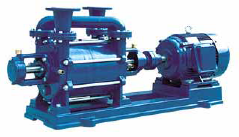 the series SK, 2SK, YK and 2YK liquid ring vacuum pumps, multi-vane impeller is fixed ecceentrically inside the pump casing. When the vanes rotate, the liquid within the casing forms a liquid ring which is concentric using the pump casing beneath the centrifugal impact, the cubage involving liquid and vanes possess a periodic adjust, so the perform of pumping be performed. Liquid ring vacuum pumps are from the capabilities of lower vitality consumption and reduced noise. They can be utilised to pump water vapor, inflammable and explosive fuel too as ordinary gases. With specific materials used for important components, they’re able to also pump corrosive gasoline. Appropriate actuating medium or often pumped medium may be chosen as actuating liquids, so the pumps can nearly take care of all extensively used for light, chemical, meals, electric energy and pharmaceutical industries, and so on.
SINGLE STAGE VACUUM PUMPS
110/220VAC Vacuum Pumps
Single stage vacuum pumps operates on 110 VAC or 220VAC. Picking the proper size pump from 1.five cfm to 9 cfm depends on your certain application. These pumps one engineered exclusively to assist you do your task speedier and much better. 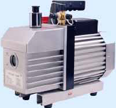 Substantial efficiency-CFM rated as ?°free air displacement.?±150 micron field rating.
Heavy duty high torque motor-assures cold climate staring.
Low operating temperature-improve efficiency and vacuum.
Forced-feed lubrication design-help decrease working temperature and far better Lubrication.
DUAL STAGE VACUUM PUMPS
110/220VAC Vacuum Pumps
Dual stage vacuum pumps operates on 110 VAC or 220VAC.State-of-the-art dual-stage design and style pulls deep vacuum to 50 microns. Layout of those one.five,three,five,eight,ten,twelve CFM pump improvements construct to the performance-proven high-quality options. Whatever your vacuum pump demands, the correct pump will go to work with you .
Dual stage design-second stage commences pumping at a decrease pressure to pull a deeper ultimate vacuum.
Preventing oil-returning design-prevents pump oil from staying sucked in to the technique if a energy reduction happens.
Gasoline ballast-speeds evacuation and keeps oil cleaner.
Substantial oil reservoir-lightweight and better dilute corrosive contaminants.
Operating principle and attributes:
The series HGL, HG pump is really a kind of single-stage and single-cylinder rotary piston vacuum pump. It really is considerably enhanced series H rotary piston pump and includes 4 patents; its standard 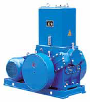 abilities have a fantastic improvement.
Rotary piston vacuum pump is really a sort of vacuum manufacturing products ideal for pumping ordinary gases and condensable gases(when a gas ballast used). The pump have to be fitted with appropriate accessories if gasoline is rich in oxygen, explosive, corrosive to ferrous metal, chemical reactive with vacuum pump oil.
Operation principle show in operating principle graph: A rotary piston with slide valve across ecentric wheel driven by shaft in the housing. Piston pole can slide and swing freely in arch track. The entire pump chamber is divided into chamber A and chamber B by piston. When shaft rotates the volume of chamber A and chamber B are altered repetitively, in order that pumping goal might be accomplished.
The series HGL, HG pump may be a backing pump when mixed with another large vacuum pump as well as operate singly. It’s widely utilized in vacuum smelting, vacuum drying, vacuum impregnation and high vacuum simulation testing,and so on.
Operating Principle and Characteristics:
The series SYF roots vacuum pump is with overflow valve. The figure-of-eight rotors are counter-rotating at a frequent speed inside the pump housing for suction and exhaust of gas. Two rotors are supported 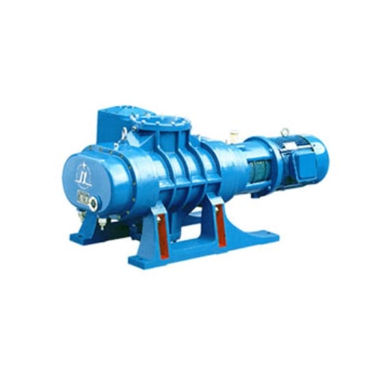 by two bearings and synchronized by a gear, which guarantees these two rotors in sure relative positions. They are really near to one another and to the housing with out real contacting, so lubrication is needless while in the working housing. The carefully balanced operating parts and high precision bevel wheels ensue the pump be operated stably and constantly underneath the condition of high-pressure distinction. Dynamic seal aspect use our patent technological innovation and imported oil seals, the vibration amount of shaft on the shaft seals is controlled to significantly less than 0.02mm.
A gravity valve is set up concerning the suction and exhaust a part of the pump. The perform from the gravity valve is as follows, once the stress difference concerning the suction and exhaust component is more than the weight of the valve, the valve opens instantly, which can make the stress big difference generally preserve within a fixed controllable value, the worth is the allowable highest stress difference to ensure the pump do the job usually and to ensure that in truth, the roots vacuum pump with overflow valve is actually a sort of overload self-protective pump.
Series SYF roots vacuum pump with overflow valve has considerably larger velocity at fairly lower inlet stress and it truly is possessed overload self-protective perform. Because it is usually a pump of dry clearance seal building, if a specific pumping pace charge and an greatest vacuum need to be obtained, it is actually required to supply a reduce inlet stress for lowering the back flow, therefore, a pump must be backed in use, roots vacuum pump really should be began quickly following its inlet stress reaches a permissible value for economization.
It’s allow to select distinctive types of pump because the backing pump for factual specifications, this kind of as oil seal pump and liquid ring vacuum pump. When pumping the gasoline containing big level of vapor, the liquid ring vacuum pump could be the best backing pump.
Use scope
The single stage oil cycle vacuum pumps of spiral slice sort of series SYF and double stage oil cycle vacuum pumps of spiral slice style from the series of 2SYF are important products for abstracting the gasoline from obturational container to have vacuum. The double stage vacuum pumps of spiral slice variety on the serie of 2SYF used for abstracting to acquire vacuum yet again to the basis of single stage pumps. It can make the system accomplish the highest level vacuum.
Functions
(1)The design of stopping oil-returning
The passage of fuel admission is specially built to avoid the returning of pumps oil delivering the abstracted container and pipeline after the pumps quit working.
(two)The style of enviromental protection
The style and design of built-in device of mist eliminating, and set oil-gas seperator about the 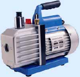 vent, each manage the pollution of oil during the course of exhausting efficiently.
(3) Aluminium alloy casing of electrical machinery
The electrical machinery use aluminium alloy casing, it’s large efficiency of heat emission, and assure very long time normal operation continously, it also has much better appearance good quality.
(four) The layout of integration
The electric machinery and pumps utilize the design of integration producing the solutions more serious and affordable.
(five) Large commencing up minute
Our item styles specially aiming on the enviroment of low temperation and electrical pressure. guaranteeing the machine commences typically at decrease temperatue of winter enviroment(?Y-5??) and low electric stress(?Y180V).
YS Series three-Phase asynchronous Motors
General introduction
YS series three-phase asynchronous motors are designed and manufactured in accordance for the national unified conventional. It has the characteristics of large efficiency, power saving, decrease noise, small vibration, lengthy support daily life, simple upkeep and huge breakaway torque. It adopts class B insulation, IP 44 of protection degree and cooling mode of IC411. Rated voltage: 380V, Rated frequency: 50HZ. This series motors are extensively applied to food machineries, blower followers as well as other machinery equipments.
YD Series multi-speed three-Phase asynchronous Motors
General introduction
This series motors are intended and produced under incorporating the benefits of the around the world counterparts, and are in total conformity with worldwide conventional of IEC. This series motors employed the approach of transforming the pole numbers to carry out speed adjustment to ensure they have fantastic attributes like modest volume, lighter weight, lower noise, very well starting up performance, reputable operation, simple servicing, etc. The main technical indexes have reached the international technical normal.
The  series motors are broadly utilized in various mechanical equipment which want stepped velocity adjustment; It allow the equipments to have compact structure, decrease noise and ability of power conserving.
Simultaneously, multi-speed motors with distinctive specification is usually built and produced in accordance on the necessities of purchaser, such as multi-speed three-phase asynchronous motor for YDT supporters and pumps. Degree of safety: IP44, or IP54, or IP55; Rated voltage: 380V, rated frequency: 50HZ.
? YL series single phase dual-capacitor asynchronous motors are developed and made in accordance with state standards, and have out-standing development of starting up and operation, are of lower noise, compact imensions,light excess weight,easy maintenance, etc.
? These motors may be broadly utilized in air compressors,pumps,supporters,refrigeration,health-related instruments as well as smaller machines,
etc. especially for occasion where only single
? phase electrical energy is available.
Safety sort: IP44 Insulation class: B
Rated voltage: 220V Cooling kind: IC0141
Duty type: steady running Rated frequency: 50Hz
YC  series heavy-duty single-phase motors are suitable for driving tiny machines and water pumps,specially for family members or workshops exactly where only single-phase electrical provide are available. Conforming to”IEC”designed with innovative procedures and made from finest supplies, the motors have pleasant visual appeal and superior efficiency.
YC series motors are of IP44, completely enclosed and fan-cooled. Motor of rated output of 3HP and below are capacitor-started, when operating below rated voltage, below 50Hz,includes a starting torque as large as 3times the rated tone and underneath 60Hz,the torque is often two.75 times the rated 1. Motors of 4HP and over are of capacitor start out and run. They’ve got the advantages of high torque,regular working, reduced the mal rise, reduced noise and greater overload performan.
Common introduction
Y2 series three-phase asynchronous motors, developed with new strategies, are renewed and upgrading merchandise according to Y series motors.
Y2 series motors are in obdurate style and fan cooled type, squirrel cage form and novel in style and wonderful in appearance, compact structure, decrease noise, higher efficiency, significant torque, excellent commencing overall performance, simple maintenance, and so on.. This series motors adopt F class insulation and created towards the insulation method assessing system in accordance of global practice.
Y2 series motors is usually widely applied to different of driving equipments for instance machine equipment, blowers, pumps, gearboxes, compressors, transporters, agricultural machines and so on.
Operating conditions
Ambient temperature: 15 forty . Altitude: no increased than 1000 meters from sea degree.
Rated voltage: 380V. Rated frequency: 50Hz,
Connection: Y connection is adopted for motors below 3KW  (3KW incorporated) and connection is adopted for some others above 4KW( 4KW integrated). Functioning ration: steady functioning program (S1).
F class Insulation, the temperature rising in the stator winding examined at 80K(by resistance process). Protection grade: around the principal physique is IP54, about the terminal box can reach IP55. Cooling process: Ic411.
The fans are generally manufactured of strengthen plastics apart from that for frame sizes H315 up to H355 are manufactured of aluminium-alloy or stamped with steel plate. Alt fan cowis are taken into shape by stret-ching with cold rolled steel plate to turn into substantial mec hanical power.
Hydraulic Auger Drives
AUGER DRIVE EARTH DRILL ATTACHMENT
TheEPG Auger Push is heavy obligation constructed and built in a chopping edge facility. EPG partnered with specialist CHINA to generate the quite greatest Skid Steer Auger Travel the North American market has to offer you. The consequence is an intense Auger Push, available in three designs, with sizeable torque for each foot abilities. Useless to say, EPG is really pleased. EPG purchases immediately from the supply and by way of an exceptional partnership with Skid Steer Options, is able to offer producer costs, without having the classic distributor mark-up.
Decide on Item Choices Over
Decide on Auger Push Model
Choose an Excavator Auger Cradle (Drive Only option obtainable)
Pick an Optional Auger Stump Planer (click on for details)
Select an optional Auger Bit
Decide on a 2nd optional Auger Bit
The CHINA made planetary gearbox delivers an tremendous quantity of torque and longevity to this Skid Steer Auger Travel. Competing companies even now use shafts inserted from the front, with issues of the shafts popping out when the retainer fails. EPG shafts are in fact inserted from the back again on a thrust plate that evenly distributes the fat. This offers you a distinct mechanical advantage and supplies much more power at the little bit. It also protects towards the shaft from popping out and makes your operation considerably safer. EPG contains a lifetime ensure from any shaft pullout. Additionally, the planetary gearbox is sealed with pre-put in lubrication, so  there is no need for servicing. All you have to do is connect your auger bit and do what you do best, operate your compact products.
AUGER DRIVE EARTH DRILL ATTACHMENT
Attributes
Aggressive, tough working, and sturdy
Market major planetary gearbox layout, routine maintenance free
Life time ensure from shaft pullout
Hydraulic Stream Selection: 7-thirty GPM (varies by design)
Hoses provided
Excavator Functioning Bodyweight
2500 Model: 4,400 – 8,800 lbs. (2 – 4 T)
3500 Product: 5,five hundred -nine,900 lbs. (two.5 – 4.5 T)
4500 Model: six,600 – eleven,000  lbs. (three – five T)
Hydraulic Auger Drives
That’s all on agricultural gearbox, interested in more?
agricultural gearbox
Farmers work challenging each and every day below demanding situations. and they rely on their gear to produce greatest productivity â all period long. Which is why top agricultural OEMs all around the entire world believe in Weasler Engineering to deliver intelligent gearbox solutions that optimize the efficiency of their machines. From application evaluation and on-web site discipline testing to the newest layout modeling and prototype investigation, Weaslerâs knowledgeable  engineering staff will function with you to build a gearbox resolution for your tools. Weasler gearboxes are offered in a broad range of HP capacities, ratios and shaft configurations.
Personalized Gearboxes
Weaslerâs personalized gearboxes are precision developed and rigorously analyzed to fulfill the most demanding requirements. In the subject, these hardworking answers transform the rotational vitality equipped by your products into the energy degree needed by the specific application at the optimum pace and electrical power necessary. Most varieties of farm machinery need a custom gearbox resolution to enhance their efficiency. Weasler engineers can work with you to design and style and build a personalized gearbox resolution that exactly satisfies your specifications and provides a mechanical edge to enhance torque and produce consistently far better performance.
Bevel Gearboxes
Weasler gives bevel gearboxes in a wide assortment of HP capacities. Choose from current ratios and shaft configurations or customise them to meet up with your distinct software needs. Our engineers will operate with you to entirely understand your requirements and size the proper gearbox for your software. If your software requires a custom push remedy, our engineers will team with you to design a bevel gearbox that satisfies your specific application to reduce stress and use on your products and increase support daily life.
agricultural gearbox
Parallel Shaft Gearboxes
Weasler Engineeringâs rugged parallel shaft gearboxes are created to meet up with a extensive range of torque needs in agriculture and other demanding marketplaces. Decide on from present ratios and shaft configurations or customise them to meet up with your application wants. Our engineers will function with you to understand your exclusive needs and size the acceptable gearbox for your software. If your software requires a personalized travel remedy, our engineers  will crew with you to design a parallel shaft gearbox that meets your actual application to reduce stress and put on on your products and extend provider daily life.
agricultural gearbox
If you would such as to understand more concerning agricultural gearbox, please fill in the call us form on our internet site.
fluid coupling
Programs:
Marine propulsion
Mixers
Boat  thrusters
Dredges
Supporters & Blowers
Shredders
Compressors
Centrifugal pumps
Recycling machinery
Grinders
Mills
Crushers
Belt conveyors
Wood chippers
Unloaded motor heat up
Smooth commence up, no belt slip
Torsio nal vibration dampening
Shock and overload defense
Substantial radial load ability
Distant handle by electric valve
Load positioning
Straightforward to preserve
For in-line and pulley applications
Dimensions fifteen â 27
Up to 1340hp
An electrically operated solenoid valve enables the fluid coupling circuit to be fed when it is turned ON. The oil drains through calibrated orifices located on the outer diameter of the fluid coupling. When it is turned OFF, it disengages the engine from the load.
The engine flywheel is related to the KPTO enter by a adaptable coupling. The output shaft can be related to the pushed device by an elastic coupling, cardan shaft or pulley.
China fluid coupling
KPTO is a variable fill fluid coupling enclosed into a casing linked to the diesel motor by signifies of a SAE housing. The KPTO has been designed to fulfill client demands combining the technical functions of a  typical Electricity Get Off with the performance of a fluid coupling.
China fluid coupling
fluid coupling
Electricity Selection
Set pace: up to 1850 KW
Variable velocity: up to 11000 KW
Velocity Assortment
Set velocity: 720 RPM â 3600 RPM
Variable  pace: 490 RPM â 3600 RPM
Commencing torque assortment
Set speed: eighty% â 275%
Solution important details
Product description
Power Transmission by means of hydraulic fluid/h2o without mechanical link amongst enter and output of driver or driven device.
Apps
Conveyors, Crushers, Shredders, Ball mills, Ring granulators, Mixers, Pumps, Followers, Boiler Feed Pumps, Industrial drives
Positive aspects
Motor Commencing with no load
Sleek acceleration of the load
Equipment and Motor defense in opposition  d-couplings.html]#to overload, restricted to the maximum torque transmitted
Motor Variety through the working torque, steering clear of an oversizing choices of the motor by the commencing torque
Reduced motor energy use
Outstanding ROI (quick pay out again interval)
High effectiveness due to the low sliding
Maximum torque transmission capability can be accomplished in the assortment of 80 up to 270% of the operating torque
A number of patterns
Tailor-produced solutions
China OEM Cardan Shaft Universal Joint Shaft Used for 40 Piercing Mill Driving air compressor for car
China OEM Cardan Shaft Universal Joint Shaft for 40 Piercing Mill Driving Air Compressor
Product Description
The Cardan Shaft Universal Joint Shaft is an essential component used in 40 piercing mill driving systems, renowned for its durability and high performance. Engineered for heavy-duty industrial applications, this shaft ensures reliable operation and longevity.
Brief Introduction
Designed to meet stringent industry standards, our Cardan shafts are crafted from high-quality alloy steel, ensuring strength and resilience under the most demanding conditions. The advanced casting and forging processes further enhance the durability and performance of our products.
Processing Flow
Our meticulous production process includes rigorous quality control measures at every stage, from raw material selection to final inspection. Each Cardan shaft undergoes a series of tests to ensure it meets our high standards.
Quality Control
Quality is our utmost priority. We implement a thorough quality control system to ensure that every product delivered meets our customers’ specifications. This includes detailed records of nonconformity, comprehensive customer feedback management, and the use of first-class production equipment, including CNC machines and machining centers.
Technical Specifications
| Structure | Type E | Flexible or Rigid | Rigid | Standard or Nonstandard | Standard |
| Material | Alloy steel | Model | SWC225E-1800 | Length | 1800mm |
| Flange DIA | 225mm | Nominal torque | 56KN.m | Coating | Heavy duty industrial paint |
| Paint color | Customization | Application | 40 piercing mill | OEM/ODM | Available |
| Certification | ISO, TUV, SGS | Price | Calculates according to model | Custom service | Available |
Packaging & Delivery
Packaging details: Standard plywood case
Delivery detail: 15-20 working days, depending on the actual production condition
Other Product Businesses
EVER-POWER GROUP offers a broad array of industrial products, including agricultural gearboxes, power output shafts, sprockets, fluid couplings, worm gear reducers, gears and racks, roller chains, pulleys and pulleys, planetary gearboxes, timing pulleys, and bushings. We pride ourselves on providing high-quality products at competitive prices with exceptional customer service. Custom drawings and samples are welcomed to meet your specific needs.
FAQs
Q1: What materials are used in the Cardan shaft?
A1: Our Cardan shafts are made from high-quality alloy steel, ensuring maximum strength and durability.
Q2: Can I customize the Cardan shaft?
A2: Yes, customization options are available. You can customize the paint color, length, and other specifications to fit your needs.
Q3: How long is the delivery time?
A3: The delivery time is typically 15-20 working days, depending on the current production schedule.
Q4: What quality control measures are in place?
A4: We have a comprehensive quality control system that includes detailed records, customer feedback management, and the use of advanced production equipment.
Q5: Do you offer other industrial products?
A5: Yes, EVER-POWER GROUP offers a wide range of industrial products, including gearboxes, sprockets, fluid couplings, and more, all customizable to meet your specific requirements.
All the content of the page is from the Internet, the content is only as a reference for product selection, our products are replacement parts and not original spare parts; we are not the holder of the original trademarks of the content, our products are only suitable for after-sales replacement parts and not original spare parts, our replacement parts can be perfectly adapted to the original spare parts; if you need to buy original spare parts, please contact the original factory to buy. If you want to buy original spare parts, please contact the original supplier for purchase.
Performance Characteristics of Cardan Shaft
The Cardan shaft is an essential component in various mechanical systems. Here are its key performance characteristics:
- High Torque Transmission: The Cardan shaft can transmit high levels of torque, which is crucial for heavy-duty applications.
- Flexibility: It offers significant flexibility, accommodating misalignments in the mechanical system without compromising performance.
- Durability: Made from robust materials, the Cardan shaft exhibits excellent resistance to wear and tear, ensuring long service life.
- Vibration Dampening: Its design helps in reducing vibrations, leading to smoother operation of the machinery.
Types and Characteristics of Cardan Shaft
There are several types of Cardan shafts available, each designed for specific applications:
- Single Cardan Shaft: Simple and cost-effective, suitable for applications with minimal misalignment.
- Double Cardan Shaft: Provides better performance in terms of reducing vibrations and accommodating greater misalignments.
- Constant Velocity (CV) Shaft: Ideal for high-speed applications, offering consistent rotational speeds without significant vibration.
The materials used in manufacturing Cardan shafts also play a crucial role:
- Steel: Most commonly used, offering excellent strength and durability.
- Aluminum: Lighter than steel, providing improved fuel efficiency in automotive applications.
- Composite Materials: These offer a balance of strength and weight reduction, ideal for aerospace applications.
Application of Cardan Shaft in Various Industries
The Cardan shaft finds applications across different industries due to its versatile characteristics:
- Automotive Industry: Used extensively in drivetrain systems to transmit torque from the engine to the wheels.
- Aerospace Industry: Essential in control systems for helicopters and other aircraft, providing reliable power transmission.
- Marine Industry: Vital for the propulsion systems in ships and boats, ensuring efficient power transfer.
- Industrial Machinery: Helps in the smooth operation of heavy machinery and manufacturing equipment.
- Agricultural Equipment: Used in tractors and other farming machinery for effective power distribution.
Future Development Trends and Opportunities of Cardan Shaft Products
The future of Cardan shaft products is promising, with several trends and opportunities emerging:
- Advanced Materials: The development of new materials will enhance the performance and reduce the weight of Cardan shafts.
- Improved Manufacturing Techniques: Advances in manufacturing processes will lead to more precise and efficient production of Cardan shafts.
- Integration of Smart Technologies: Incorporating sensors and smart technology will allow for real-time monitoring and maintenance.
- Growth in Electric Vehicles: The rise of electric vehicles presents new opportunities for Cardan shaft applications in innovative drivetrain systems.
These trends indicate a bright future for Cardan shaft products, with continuous improvements and expanding applications.
How to Choose a Suitable Cardan Shaft
Choosing the right Cardan shaft involves careful consideration of several factors:
- Determine Application Requirements: Understand the specific needs of your application, including the type of machinery and expected performance.
- Evaluating Power Requirements: Ensure the shaft can handle the power output of the machinery.
- Check Speed and Torque Specifications: Verify that the shaft can operate within the required speed and torque limits.
- Measuring the Length of the Shaft: Accurate measurements are crucial for proper fit and function.
- Evaluate Connection Type: Ensure the shaft’s connections are compatible with your machinery.
- Check Safety Features: Consider the safety mechanisms in place to prevent failures and ensure safe operation.
Conclusion
The Cardan shaft is a critical component in many mechanical systems, offering high torque transmission, flexibility, and durability. Its applications span across various industries, including automotive, aerospace, marine, industrial machinery, and agricultural equipment. The future development trends and opportunities for Cardan shaft products are promising, with advancements in materials, manufacturing techniques, and smart technologies. By carefully considering application requirements, power needs, speed and torque specifications, shaft length, connection types, and safety features, one can select the most suitable Cardan shaft for their needs.
Author: Dream
China Custom Cardan Shaft, Universal Joint, Shaft Coupling, Universal Coupling for Rolling Mill with Best Sales
High-Quality Custom Cardan Shafts and Universal Joints for Rolling Mills
Product Description
Cardan Shaft, Universal Joint, Universal Coupling For Rolling Mill
By collaborating with leading domestic manufacturers, we provide a comprehensive range of couplings to meet diverse requirements.
The universal coupling shaft is designed to link the driving shaft and driven shaft of two distinct mechanisms, facilitating effective torque transfer.
1. Scope of Application
SWC medium-sized universal joints are predominantly utilized in mechanical applications such as rolling mills, piercing machines, straighteners, crushers, and ship drives. These products are widely recognized for their versatility. They feature a flange diameter range of 160-620mm, a rated torque transmission range of 16-1000kN.m, and an axis angle of 15°.
2. Structural Features
The universal coupling capitalizes on its mechanical design to allow continuous rotation of the connected shafts, even when they are not on the same axis. This ensures reliable transmission of torque and movement.
The medium-sized universal coupling is characterized by its compact structure, high transmission torque, extended service life, and resilience under harsh working conditions.
Additional Product Offerings
EVER-POWER GROUP specializes in a variety of industrial products, including agricultural gearboxes, power output shafts, sprockets, fluid couplings, worm gear reducers, gears and racks, roller chains, pulleys, planetary gearboxes, timing pulleys, and bushings. We pride ourselves on delivering superior quality products at competitive prices, with exceptional customer service. Custom drawings and samples are welcome.
FAQs
1. What are the primary applications of the SWC medium-sized universal joints?
These universal joints are mainly used in rolling mills, piercing machines, straighteners, crushers, and ship drives.
2. What is the flange diameter range for these universal joints?
The flange diameter ranges from 160mm to 620mm.
3. Can the universal coupling be used under severe working conditions?
Yes, the medium-sized universal coupling is designed for long-term use under severe working conditions.
4. What other products does EVER-POWER GROUP supply?
We supply agricultural gearboxes, power output shafts, sprockets, fluid couplings, worm gear reducers, gears and racks, roller chains, pulleys, planetary gearboxes, timing pulleys, and bushings.
5. Are custom drawings and samples accepted for product customization?
Yes, we welcome customers to provide custom drawings and samples for product customization.
All the content of the page is from the Internet, the content is only as a reference for product selection, our products are replacement parts and not original spare parts; we are not the holder of the original trademarks of the content, our products are only suitable for after-sales replacement parts and not original spare parts, our replacement parts can be perfectly adapted to the original spare parts; if you need to buy original spare parts, please contact the original factory to buy. If you want to buy original spare parts, please contact the original supplier for purchase.
Performance Characteristics of Cardan Shaft
The Cardan shaft is an essential component in various mechanical systems. Here are its key performance characteristics:
- High Torque Transmission: The Cardan shaft can transmit high levels of torque, which is crucial for heavy-duty applications.
- Flexibility: It offers significant flexibility, accommodating misalignments in the mechanical system without compromising performance.
- Durability: Made from robust materials, the Cardan shaft exhibits excellent resistance to wear and tear, ensuring long service life.
- Vibration Dampening: Its design helps in reducing vibrations, leading to smoother operation of the machinery.
Types and Characteristics of Cardan Shaft
There are several types of Cardan shafts available, each designed for specific applications:
- Single Cardan Shaft: Simple and cost-effective, suitable for applications with minimal misalignment.
- Double Cardan Shaft: Provides better performance in terms of reducing vibrations and accommodating greater misalignments.
- Constant Velocity (CV) Shaft: Ideal for high-speed applications, offering consistent rotational speeds without significant vibration.
The materials used in manufacturing Cardan shafts also play a crucial role:
- Steel: Most commonly used, offering excellent strength and durability.
- Aluminum: Lighter than steel, providing improved fuel efficiency in automotive applications.
- Composite Materials: These offer a balance of strength and weight reduction, ideal for aerospace applications.
Application of Cardan Shaft in Various Industries
The Cardan shaft finds applications across different industries due to its versatile characteristics:
- Automotive Industry: Used extensively in drivetrain systems to transmit torque from the engine to the wheels.
- Aerospace Industry: Essential in control systems for helicopters and other aircraft, providing reliable power transmission.
- Marine Industry: Vital for the propulsion systems in ships and boats, ensuring efficient power transfer.
- Industrial Machinery: Helps in the smooth operation of heavy machinery and manufacturing equipment.
- Agricultural Equipment: Used in tractors and other farming machinery for effective power distribution.
Future Development Trends and Opportunities of Cardan Shaft Products
The future of Cardan shaft products is promising, with several trends and opportunities emerging:
- Advanced Materials: The development of new materials will enhance the performance and reduce the weight of Cardan shafts.
- Improved Manufacturing Techniques: Advances in manufacturing processes will lead to more precise and efficient production of Cardan shafts.
- Integration of Smart Technologies: Incorporating sensors and smart technology will allow for real-time monitoring and maintenance.
- Growth in Electric Vehicles: The rise of electric vehicles presents new opportunities for Cardan shaft applications in innovative drivetrain systems.
These trends indicate a bright future for Cardan shaft products, with continuous improvements and expanding applications.
How to Choose a Suitable Cardan Shaft
Choosing the right Cardan shaft involves careful consideration of several factors:
- Determine Application Requirements: Understand the specific needs of your application, including the type of machinery and expected performance.
- Evaluating Power Requirements: Ensure the shaft can handle the power output of the machinery.
- Check Speed and Torque Specifications: Verify that the shaft can operate within the required speed and torque limits.
- Measuring the Length of the Shaft: Accurate measurements are crucial for proper fit and function.
- Evaluate Connection Type: Ensure the shaft’s connections are compatible with your machinery.
- Check Safety Features: Consider the safety mechanisms in place to prevent failures and ensure safe operation.
Conclusion
The Cardan shaft is a critical component in many mechanical systems, offering high torque transmission, flexibility, and durability. Its applications span across various industries, including automotive, aerospace, marine, industrial machinery, and agricultural equipment. The future development trends and opportunities for Cardan shaft products are promising, with advancements in materials, manufacturing techniques, and smart technologies. By carefully considering application requirements, power needs, speed and torque specifications, shaft length, connection types, and safety features, one can select the most suitable Cardan shaft for their needs.
Author: Dream
China OEM SWC Series-Medium-Duty Designs Cardan Shaft air compressor lowes
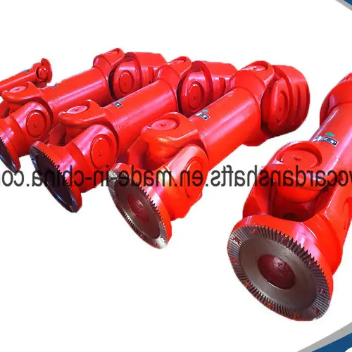
China OEM SWC Series-Medium-Duty Designs Cardan Shaft Air Compressor Lowes
Product Description
The SWC Series-Medium-Duty Designs Cardan Shaft is a high-performance component specifically engineered for industrial applications. This robust cardan shaft is crafted from premium alloy steel, ensuring durability and reliability in demanding environments. It is renowned for its exceptional flexibility and rigidity, adapting seamlessly to various mechanical setups.
Processing Flow
Our cardan shafts undergo a meticulous manufacturing process, including precision machining, heat treatment, and rigorous quality checks. This ensures that each unit meets stringent performance standards.
Applications
The SWC Series is versatile and widely used in various industries, including heavy machinery, automotive, and industrial equipment. Its adaptability makes it an indispensable component in many engineering solutions.
Quality Control
Quality is our utmost priority. Each cardan shaft is subjected to a comprehensive quality control system to ensure it meets international standards such as ISO, TUV, and SGS. This guarantees that our products deliver optimal performance and reliability.
Product Specifications
| Structure | Universal | Flexible or Rigid | Rigid | Standard or Nonstandard | Nonstandard |
| Material | Alloy steel | Brand name | HangZhou XIHU (WEST LAKE) DIS. | Place of origin | Zhejiang, China |
| Model | SWC Medium | Raw materials | Heat treatment | Length | Customization |
| Flange DIA | 160mm~620mm | Nominal torque | Depends on model | Coating | Heavy duty industrial paint |
| Paint color | Customization | Application | Industrial equipment | OEM/ODM | Available |
| Certification | ISO, TUV, SGS | Price | Calculate according to model | Custom service | Available |
Packaging & Delivery
Packaging details: Standard plywood case.
Delivery detail: 15-20 working days, depending on the actual produce condition.
FAQ
Q1: What material is the Cardan Shaft made of?
A1: The Cardan Shaft is made of premium alloy steel, ensuring high durability and performance.
Q2: Can the paint color be customized?
A2: Yes, the paint color can be customized according to your preferences.
Q3: What certifications do your Cardan Shafts have?
A3: Our Cardan Shafts are certified by ISO, TUV, and SGS standards.
Q4: What are the applications of the SWC Series Cardan Shaft?
A4: It is widely used in industrial equipment and heavy machinery due to its exceptional performance and adaptability.
Q5: Are OEM/ODM services available?
A5: Yes, we offer OEM/ODM services to meet specific customer requirements.
Other Products
EVER-POWER GROUP is a leading supplier of various industrial products such as agricultural gearboxes, power output shafts, sprockets, fluid couplings, worm gear reducers, gears and racks, roller chains, pulleys, planetary gearboxes, timing pulleys, and bushings. We pride ourselves on offering high-quality products at competitive prices along with exceptional customer service. We welcome custom orders based on your drawings or samples.
All the content of the page is from the Internet, the content is only as a reference for product selection, our products are replacement parts and not original spare parts; we are not the holder of the original trademarks of the content, our products are only suitable for after-sales replacement parts and not original spare parts, our replacement parts can be perfectly adapted to the original spare parts; if you need to buy original spare parts, please contact the original factory to buy. If you want to buy original spare parts, please contact the original supplier for purchase.
Performance Characteristics of Cardan Shaft
The Cardan shaft is an essential component in various mechanical systems. Here are its key performance characteristics:
- High Torque Transmission: The Cardan shaft can transmit high levels of torque, which is crucial for heavy-duty applications.
- Flexibility: It offers significant flexibility, accommodating misalignments in the mechanical system without compromising performance.
- Durability: Made from robust materials, the Cardan shaft exhibits excellent resistance to wear and tear, ensuring long service life.
- Vibration Dampening: Its design helps in reducing vibrations, leading to smoother operation of the machinery.
Types and Characteristics of Cardan Shaft
There are several types of Cardan shafts available, each designed for specific applications:
- Single Cardan Shaft: Simple and cost-effective, suitable for applications with minimal misalignment.
- Double Cardan Shaft: Provides better performance in terms of reducing vibrations and accommodating greater misalignments.
- Constant Velocity (CV) Shaft: Ideal for high-speed applications, offering consistent rotational speeds without significant vibration.
The materials used in manufacturing Cardan shafts also play a crucial role:
- Steel: Most commonly used, offering excellent strength and durability.
- Aluminum: Lighter than steel, providing improved fuel efficiency in automotive applications.
- Composite Materials: These offer a balance of strength and weight reduction, ideal for aerospace applications.
Application of Cardan Shaft in Various Industries
The Cardan shaft finds applications across different industries due to its versatile characteristics:
- Automotive Industry: Used extensively in drivetrain systems to transmit torque from the engine to the wheels.
- Aerospace Industry: Essential in control systems for helicopters and other aircraft, providing reliable power transmission.
- Marine Industry: Vital for the propulsion systems in ships and boats, ensuring efficient power transfer.
- Industrial Machinery: Helps in the smooth operation of heavy machinery and manufacturing equipment.
- Agricultural Equipment: Used in tractors and other farming machinery for effective power distribution.
Future Development Trends and Opportunities of Cardan Shaft Products
The future of Cardan shaft products is promising, with several trends and opportunities emerging:
- Advanced Materials: The development of new materials will enhance the performance and reduce the weight of Cardan shafts.
- Improved Manufacturing Techniques: Advances in manufacturing processes will lead to more precise and efficient production of Cardan shafts.
- Integration of Smart Technologies: Incorporating sensors and smart technology will allow for real-time monitoring and maintenance.
- Growth in Electric Vehicles: The rise of electric vehicles presents new opportunities for Cardan shaft applications in innovative drivetrain systems.
These trends indicate a bright future for Cardan shaft products, with continuous improvements and expanding applications.
How to Choose a Suitable Cardan Shaft
Choosing the right Cardan shaft involves careful consideration of several factors:
- Determine Application Requirements: Understand the specific needs of your application, including the type of machinery and expected performance.
- Evaluating Power Requirements: Ensure the shaft can handle the power output of the machinery.
- Check Speed and Torque Specifications: Verify that the shaft can operate within the required speed and torque limits.
- Measuring the Length of the Shaft: Accurate measurements are crucial for proper fit and function.
- Evaluate Connection Type: Ensure the shaft’s connections are compatible with your machinery.
- Check Safety Features: Consider the safety mechanisms in place to prevent failures and ensure safe operation.
Conclusion
The Cardan shaft is a critical component in many mechanical systems, offering high torque transmission, flexibility, and durability. Its applications span across various industries, including automotive, aerospace, marine, industrial machinery, and agricultural equipment. The future development trends and opportunities for Cardan shaft products are promising, with advancements in materials, manufacturing techniques, and smart technologies. By carefully considering application requirements, power needs, speed and torque specifications, shaft length, connection types, and safety features, one can select the most suitable Cardan shaft for their needs.
Author: Dream
China wholesaler Agricultural Farm Tractor Truck Cardan Universal Joint Durable Pto Shaft for Rotary Tiller Shear Bolt Torque Limiter air compressor parts
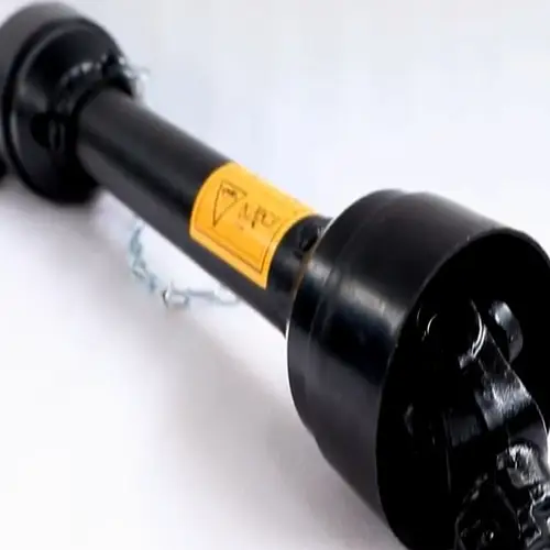
Agricultural Farm Tractor Truck PTO Shaft: Durable Solutions for Rotary Tiller Shear Bolt Torque Limiter
Product Description
The Agricultural Farm Tractor Truck Cardan Universal Joint Durable PTO Shaft is meticulously engineered to power rotary tillers and other farm implements effectively. This robust PTO shaft ensures seamless power transmission from tractors to various attachments, enhancing operational efficiency and reliability.
Power Take-Off Shafts for All Applications
A power take-off (PTO) is a sophisticated mechanism that transfers power from a running engine to an application, such as agricultural implements or industrial machines. This device is commonly a splined drive shaft connected to a tractor or truck, enabling direct power transfer to tools with compatible fittings.
Semi-permanently mounted PTOs are also prevalent in industrial and marine engines, utilizing drive shafts and bolted joints to channel power to secondary implements or accessories. In marine contexts, these shafts often power essential equipment like fire pumps, underscoring their versatility and critical importance in various sectors.
High-Quality PTO Shaft Parts and Accessories
We offer a comprehensive range of premium PTO shaft parts and accessories, including clutches, tubes, and yokes, designed to meet the diverse needs of your tractor and implements. Our extensive PTO driveline collection is available at competitive rates, ensuring optimal performance and value.
Understanding Power Take-Off (PTO)
What does a power take-off do?
A power take-off (PTO) transfers mechanical power from an engine to another piece of equipment. This allows the primary energy source to provide power to additional machinery that lacks its own engine or motor. For instance, a PTO can enable a tractor engine to power a jackhammer effectively.
What’s the difference between 540 and 1000 PTO?
When a PTO shaft operates at 540 RPM, the ratio must be adjusted (geared up or down) to match the implement’s requirements, typically at higher RPMs. Conversely, a 1000 RPM PTO almost doubles the speed, requiring less gearing up in the implement, thus streamlining the power transfer process.
PTO Shaft Specifications
| Function | Power transmission |
| Use | Tractors and various farm implements |
| Place of Origin | Hangzhou, Zhejiang, China (Mainland) |
| Brand Name | EPT |
| Yoke Type | Push pin, quick release, collar, double push pin, bolt pins, split pins |
| Processing of Yoke | Forging |
| Plastic Cover | YW, BW, YS, BS |
| Color | Yellow, black |
| Series | T series, L series, S series |
| Tube Type | Triangular, star, lemon |
| Processing of Tube | Cold drawn |
| Spline Type | 1 3/8″ Z6, 1 3/8″ Z21, 1 3/4″ Z20, 1 1/8″ Z6, 1 3/4″ Z6 |
Related Products
Explore our diverse range of products tailored for industrial applications, including agricultural gearboxes, power output shafts, sprockets, fluid couplings, worm gear reducers, gears and racks, roller chains, pulleys, and planetary gearboxes. Our offerings stand out for their exceptional quality, competitive prices, and attentive service. We welcome customers to customize orders with drawings and samples.
FAQs
1. What is the main function of a PTO shaft?
A PTO shaft transfers mechanical power from a tractor’s engine to various implements, enabling them to operate efficiently without their own power source.
2. How does a 540 RPM PTO differ from a 1000 RPM PTO?
A 540 RPM PTO requires more gearing up to match implement needs, whereas a 1000 RPM PTO operates nearly double in speed, reducing the need for additional gearing.
3. What types of yokes are available for PTO shafts?
We offer several yoke types, including push pin, quick release, collar, double push pin, bolt pins, and split pins.
4. What materials are used in processing PTO shaft tubes?
PTO shaft tubes are processed using cold drawing techniques to ensure durability and precision.
5. Can customers request customizations for PTO shaft products?
Yes, we welcome customers to submit drawings and samples for customized PTO shaft products to meet specific requirements.
All the content of the page is from the Internet, the content is only as a reference for product selection, our products are replacement parts and not original spare parts; we are not the holder of the original trademarks of the content, our products are only suitable for after-sales replacement parts and not original spare parts, our replacement parts can be perfectly adapted to the original spare parts; if you need to buy original spare parts, please contact the original factory to buy. If you want to buy original spare parts, please contact the original supplier for purchase.
Performance Characteristics of Cardan Shaft
The Cardan shaft is an essential component in various mechanical systems. Here are its key performance characteristics:
- High Torque Transmission: The Cardan shaft can transmit high levels of torque, which is crucial for heavy-duty applications.
- Flexibility: It offers significant flexibility, accommodating misalignments in the mechanical system without compromising performance.
- Durability: Made from robust materials, the Cardan shaft exhibits excellent resistance to wear and tear, ensuring long service life.
- Vibration Dampening: Its design helps in reducing vibrations, leading to smoother operation of the machinery.
Types and Characteristics of Cardan Shaft
There are several types of Cardan shafts available, each designed for specific applications:
- Single Cardan Shaft: Simple and cost-effective, suitable for applications with minimal misalignment.
- Double Cardan Shaft: Provides better performance in terms of reducing vibrations and accommodating greater misalignments.
- Constant Velocity (CV) Shaft: Ideal for high-speed applications, offering consistent rotational speeds without significant vibration.
The materials used in manufacturing Cardan shafts also play a crucial role:
- Steel: Most commonly used, offering excellent strength and durability.
- Aluminum: Lighter than steel, providing improved fuel efficiency in automotive applications.
- Composite Materials: These offer a balance of strength and weight reduction, ideal for aerospace applications.
Application of Cardan Shaft in Various Industries
The Cardan shaft finds applications across different industries due to its versatile characteristics:
- Automotive Industry: Used extensively in drivetrain systems to transmit torque from the engine to the wheels.
- Aerospace Industry: Essential in control systems for helicopters and other aircraft, providing reliable power transmission.
- Marine Industry: Vital for the propulsion systems in ships and boats, ensuring efficient power transfer.
- Industrial Machinery: Helps in the smooth operation of heavy machinery and manufacturing equipment.
- Agricultural Equipment: Used in tractors and other farming machinery for effective power distribution.
Future Development Trends and Opportunities of Cardan Shaft Products
The future of Cardan shaft products is promising, with several trends and opportunities emerging:
- Advanced Materials: The development of new materials will enhance the performance and reduce the weight of Cardan shafts.
- Improved Manufacturing Techniques: Advances in manufacturing processes will lead to more precise and efficient production of Cardan shafts.
- Integration of Smart Technologies: Incorporating sensors and smart technology will allow for real-time monitoring and maintenance.
- Growth in Electric Vehicles: The rise of electric vehicles presents new opportunities for Cardan shaft applications in innovative drivetrain systems.
These trends indicate a bright future for Cardan shaft products, with continuous improvements and expanding applications.
How to Choose a Suitable Cardan Shaft
Choosing the right Cardan shaft involves careful consideration of several factors:
- Determine Application Requirements: Understand the specific needs of your application, including the type of machinery and expected performance.
- Evaluating Power Requirements: Ensure the shaft can handle the power output of the machinery.
- Check Speed and Torque Specifications: Verify that the shaft can operate within the required speed and torque limits.
- Measuring the Length of the Shaft: Accurate measurements are crucial for proper fit and function.
- Evaluate Connection Type: Ensure the shaft’s connections are compatible with your machinery.
- Check Safety Features: Consider the safety mechanisms in place to prevent failures and ensure safe operation.
Conclusion
The Cardan shaft is a critical component in many mechanical systems, offering high torque transmission, flexibility, and durability. Its applications span across various industries, including automotive, aerospace, marine, industrial machinery, and agricultural equipment. The future development trends and opportunities for Cardan shaft products are promising, with advancements in materials, manufacturing techniques, and smart technologies. By carefully considering application requirements, power needs, speed and torque specifications, shaft length, connection types, and safety features, one can select the most suitable Cardan shaft for their needs.
Author: Dream
China Custom Cwf-C2304kja-17 Cardan Shaft for CHINAMFG Noah with high quality
High-Quality Custom Cwf-C2304kja-17 Cardan Shaft for Toyota Noah
Product Description
As a distinguished manufacturer of propeller shafts, we offer an extensive selection of over 1000 items catering to a variety of car models. Our premium products are widely distributed across North America, Europe, Australia, South Korea, the Middle East, Southeast Asia, and other regions. We provide components suitable for European, American, Japanese, and Korean vehicles.
Our Advantages
- Comprehensive range of products
- MOQ: 1 piece/item
- Timely delivery
- Warranty: 1 year
Product Specifications
| OE NUMBER | 37110-28440 |
|---|---|
| TYPE | Toyota Noah CWF-C2304KJA-17 |
| MATERIAL | STEEL |
| BALANCE STANDARD | G16, 3200 RPM |
Explore Our Other Products
EVER-POWER GROUP excels in supplying a wide array of industrial products, including agricultural gearboxes, power output shafts, sprockets, fluid couplings, worm gear reducers, gears and racks, roller chains, pulleys, planetary gearboxes, timing pulleys, bushings, and more. We pride ourselves on delivering high-caliber products, competitive prices, and exceptional service. Custom drawings and samples are welcome for personalized manufacturing.
FAQs
1. What is the MOQ for your Cardan shafts?
The MOQ is 1 piece/item.
2. Which regions do you distribute your products to?
Our products are mainly sold in North America, Europe, Australia, South Korea, the Middle East, Southeast Asia, and other regions.
3. What is the warranty period for your Cardan shafts?
The warranty period is 1 year.
4. Which vehicle models are compatible with your Cardan shafts?
Our Cardan shafts are suitable for European, American, Japanese, and Korean vehicles, including the Toyota Noah model.
5. Do you accept custom orders based on drawings and samples?
Yes, we welcome custom orders and can manufacture products based on your drawings and samples.
All the content of the page is from the Internet, the content is only as a reference for product selection, our products are replacement parts and not original spare parts; we are not the holder of the original trademarks of the content, our products are only suitable for after-sales replacement parts and not original spare parts, our replacement parts can be perfectly adapted to the original spare parts; if you need to buy original spare parts, please contact the original factory to buy. If you want to buy original spare parts, please contact the original supplier for purchase.
Performance Characteristics of Cardan Shaft
The Cardan shaft is an essential component in various mechanical systems. Here are its key performance characteristics:
- High Torque Transmission: The Cardan shaft can transmit high levels of torque, which is crucial for heavy-duty applications.
- Flexibility: It offers significant flexibility, accommodating misalignments in the mechanical system without compromising performance.
- Durability: Made from robust materials, the Cardan shaft exhibits excellent resistance to wear and tear, ensuring long service life.
- Vibration Dampening: Its design helps in reducing vibrations, leading to smoother operation of the machinery.
Types and Characteristics of Cardan Shaft
There are several types of Cardan shafts available, each designed for specific applications:
- Single Cardan Shaft: Simple and cost-effective, suitable for applications with minimal misalignment.
- Double Cardan Shaft: Provides better performance in terms of reducing vibrations and accommodating greater misalignments.
- Constant Velocity (CV) Shaft: Ideal for high-speed applications, offering consistent rotational speeds without significant vibration.
The materials used in manufacturing Cardan shafts also play a crucial role:
- Steel: Most commonly used, offering excellent strength and durability.
- Aluminum: Lighter than steel, providing improved fuel efficiency in automotive applications.
- Composite Materials: These offer a balance of strength and weight reduction, ideal for aerospace applications.
Application of Cardan Shaft in Various Industries
The Cardan shaft finds applications across different industries due to its versatile characteristics:
- Automotive Industry: Used extensively in drivetrain systems to transmit torque from the engine to the wheels.
- Aerospace Industry: Essential in control systems for helicopters and other aircraft, providing reliable power transmission.
- Marine Industry: Vital for the propulsion systems in ships and boats, ensuring efficient power transfer.
- Industrial Machinery: Helps in the smooth operation of heavy machinery and manufacturing equipment.
- Agricultural Equipment: Used in tractors and other farming machinery for effective power distribution.
Future Development Trends and Opportunities of Cardan Shaft Products
The future of Cardan shaft products is promising, with several trends and opportunities emerging:
- Advanced Materials: The development of new materials will enhance the performance and reduce the weight of Cardan shafts.
- Improved Manufacturing Techniques: Advances in manufacturing processes will lead to more precise and efficient production of Cardan shafts.
- Integration of Smart Technologies: Incorporating sensors and smart technology will allow for real-time monitoring and maintenance.
- Growth in Electric Vehicles: The rise of electric vehicles presents new opportunities for Cardan shaft applications in innovative drivetrain systems.
These trends indicate a bright future for Cardan shaft products, with continuous improvements and expanding applications.
How to Choose a Suitable Cardan Shaft
Choosing the right Cardan shaft involves careful consideration of several factors:
- Determine Application Requirements: Understand the specific needs of your application, including the type of machinery and expected performance.
- Evaluating Power Requirements: Ensure the shaft can handle the power output of the machinery.
- Check Speed and Torque Specifications: Verify that the shaft can operate within the required speed and torque limits.
- Measuring the Length of the Shaft: Accurate measurements are crucial for proper fit and function.
- Evaluate Connection Type: Ensure the shaft’s connections are compatible with your machinery.
- Check Safety Features: Consider the safety mechanisms in place to prevent failures and ensure safe operation.
Conclusion
The Cardan shaft is a critical component in many mechanical systems, offering high torque transmission, flexibility, and durability. Its applications span across various industries, including automotive, aerospace, marine, industrial machinery, and agricultural equipment. The future development trends and opportunities for Cardan shaft products are promising, with advancements in materials, manufacturing techniques, and smart technologies. By carefully considering application requirements, power needs, speed and torque specifications, shaft length, connection types, and safety features, one can select the most suitable Cardan shaft for their needs.
Author: Dream
China manufacturer Wuxi CHINAMFG Brand SWC Type Cardan Shaft Universal Joint Shaft 12v air compressor
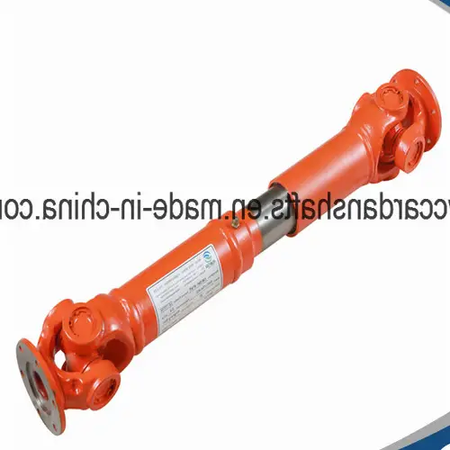
Wuxi CHINAMFG SWC Type Cardan Shaft Universal Joint & 12v Air Compressor
Product Description
Introducing the SWC-I75A-450 Industrial Cardan Shaft, an engineering marvel designed to provide unparalleled performance in various industrial applications. Crafted from high-grade alloy steel, this universal joint shaft is built to last, ensuring longevity and reliability under strenuous conditions. The meticulous design and rigorous quality control make it an ideal choice for high-precision machinery.
Specifications
| Structure | Type A | Flexible or Rigid | Rigid | Standard or Nonstandard | Standard |
| Material | Alloy Steel | Brand Name | Wuxi CHINAMFG | Place of Origin | Zhejiang, China |
| Model | SWC-I75A-450 | Raw Materials | Castings/Forgings | Length | 450mm |
| Flange Diameter | 75mm | Nominal Torque | 0.4KN.m | Coating | Heavy Duty Industrial Paint |
| Paint Color | Customization | Application | Equipment | OEM/ODM | Available |
| Certification | ISO, TUV, SGS | Price | Calculated according to model | Custom Service | Available |
Packaging & Delivery
Packaging Details: Standard plywood case
Delivery Details: 15-20 working days, depending on the actual production conditions.
FAQs
Q: Can you do OEM? And what is your minimum order?
A: Yes, absolutely. Generally, the minimum order is 1 set. Most of our products are customized. Each order is produced after the customer confirms the drawing, so we do not keep stock.
Q: How does your factory ensure quality control?
A: Quality is a priority! We control quality from the beginning to the end. Our QC department ensures that every product meets high standards, with detailed records for nonconforming products to prevent recurrence. We also have first-class production equipment, including CNC machines and machining centers.
Q: What materials are used in the manufacturing of this Cardan Shaft?
A: The SWC-I75A-450 Cardan Shaft is made of high-quality alloy steel, ensuring durability and reliability in industrial applications.
Q: What certifications do your products have?
A: Our products are certified by ISO, TUV, and SGS, meeting international quality standards.
Q: What is the delivery time for your products?
A: The delivery time is typically 15-20 working days, depending on the actual production conditions.
Explore More Products
In addition to the SWC Type Cardan Shaft, EVER-POWER GROUP offers a wide range of industrial products including agricultural gearboxes, power output shafts, sprockets, fluid couplings, worm gear reducers, gears and racks, roller chains, pulleys and pulleys, planetary gearboxes, timing pulleys, and bushings. Our high-quality products come with attractive prices and considerate services. Customers are welcome to customize drawings and samples to meet their specific needs.
All the content of the page is from the Internet, the content is only as a reference for product selection, our products are replacement parts and not original spare parts; we are not the holder of the original trademarks of the content, our products are only suitable for after-sales replacement parts and not original spare parts, our replacement parts can be perfectly adapted to the original spare parts; if you need to buy original spare parts, please contact the original factory to buy. If you want to buy original spare parts, please contact the original supplier for purchase.
Performance Characteristics of Cardan Shaft
The Cardan shaft is an essential component in various mechanical systems. Here are its key performance characteristics:
- High Torque Transmission: The Cardan shaft can transmit high levels of torque, which is crucial for heavy-duty applications.
- Flexibility: It offers significant flexibility, accommodating misalignments in the mechanical system without compromising performance.
- Durability: Made from robust materials, the Cardan shaft exhibits excellent resistance to wear and tear, ensuring long service life.
- Vibration Dampening: Its design helps in reducing vibrations, leading to smoother operation of the machinery.
Types and Characteristics of Cardan Shaft
There are several types of Cardan shafts available, each designed for specific applications:
- Single Cardan Shaft: Simple and cost-effective, suitable for applications with minimal misalignment.
- Double Cardan Shaft: Provides better performance in terms of reducing vibrations and accommodating greater misalignments.
- Constant Velocity (CV) Shaft: Ideal for high-speed applications, offering consistent rotational speeds without significant vibration.
The materials used in manufacturing Cardan shafts also play a crucial role:
- Steel: Most commonly used, offering excellent strength and durability.
- Aluminum: Lighter than steel, providing improved fuel efficiency in automotive applications.
- Composite Materials: These offer a balance of strength and weight reduction, ideal for aerospace applications.
Application of Cardan Shaft in Various Industries
The Cardan shaft finds applications across different industries due to its versatile characteristics:
- Automotive Industry: Used extensively in drivetrain systems to transmit torque from the engine to the wheels.
- Aerospace Industry: Essential in control systems for helicopters and other aircraft, providing reliable power transmission.
- Marine Industry: Vital for the propulsion systems in ships and boats, ensuring efficient power transfer.
- Industrial Machinery: Helps in the smooth operation of heavy machinery and manufacturing equipment.
- Agricultural Equipment: Used in tractors and other farming machinery for effective power distribution.
Future Development Trends and Opportunities of Cardan Shaft Products
The future of Cardan shaft products is promising, with several trends and opportunities emerging:
- Advanced Materials: The development of new materials will enhance the performance and reduce the weight of Cardan shafts.
- Improved Manufacturing Techniques: Advances in manufacturing processes will lead to more precise and efficient production of Cardan shafts.
- Integration of Smart Technologies: Incorporating sensors and smart technology will allow for real-time monitoring and maintenance.
- Growth in Electric Vehicles: The rise of electric vehicles presents new opportunities for Cardan shaft applications in innovative drivetrain systems.
These trends indicate a bright future for Cardan shaft products, with continuous improvements and expanding applications.
How to Choose a Suitable Cardan Shaft
Choosing the right Cardan shaft involves careful consideration of several factors:
- Determine Application Requirements: Understand the specific needs of your application, including the type of machinery and expected performance.
- Evaluating Power Requirements: Ensure the shaft can handle the power output of the machinery.
- Check Speed and Torque Specifications: Verify that the shaft can operate within the required speed and torque limits.
- Measuring the Length of the Shaft: Accurate measurements are crucial for proper fit and function.
- Evaluate Connection Type: Ensure the shaft’s connections are compatible with your machinery.
- Check Safety Features: Consider the safety mechanisms in place to prevent failures and ensure safe operation.
Conclusion
The Cardan shaft is a critical component in many mechanical systems, offering high torque transmission, flexibility, and durability. Its applications span across various industries, including automotive, aerospace, marine, industrial machinery, and agricultural equipment. The future development trends and opportunities for Cardan shaft products are promising, with advancements in materials, manufacturing techniques, and smart technologies. By carefully considering application requirements, power needs, speed and torque specifications, shaft length, connection types, and safety features, one can select the most suitable Cardan shaft for their needs.
Author: Dream
China Best Sales Agriculture Machinery OEM ODM Cardan Transmission Tractor Parts Pto Drive Shaft small air compressor
![]()
China Best Sales Agriculture Machinery OEM ODM Cardan Transmission Tractor Parts PTO Drive Shaft
Product Description
Our PTO (Power Take-Off) shaft is a critical component designed for transmitting power from the tractor to various attached agricultural machinery. Engineered with precision, the PTO drive shaft ensures optimal performance and durability, accommodating the diverse needs of farmers and agricultural professionals. Featuring unparalleled strength and a robust build, our PTO shafts are suitable for a myriad of applications, offering reliability in the field.
Product Parameters
- High torque capacity
- Adjustable length for versatile usage
- Corrosion-resistant materials
- Seamless power transmission
Packaging & Shipping
Packing: Normal packing or customized according to your requirements. Ensuring safe, complete, and speedy delivery of goods to customers.
Shipping: By sea
Payment Terms: T/T
After Sales Service
After Service: We offer a 12-month guarantee on the main parts. If you require replacement parts urgently, we can dispatch them via air express or include them in your next order.
FAQs
1. Q: How can I get a price list for these products?
A: Please specify the product model you are interested in so that we can provide you with an accurate quotation. Given our extensive product range, we typically do not offer a comprehensive price list.
2. Q: What are your business terms?
A: Shipment time is typically 25-40 days after payment. We ship by sea from HangZhou port, China. Payment is made via T/T, and we provide a 1-year warranty.
3. Q: How do I place an order?
A: Please send us your inquiry list, and we will respond within two working days.
4. Q: What if the product I need is not listed in your catalog?
A: We can develop the product according to your drawing or sample.
5. Q: Why should I choose your company as a supplier?
A: We offer numerous advantages over our competitors, including over 30 years of manufacturing experience, a wide range of agricultural machinery, professional sales staff, superior product quality, faster delivery times, and a lower repair rate.
Other Products
EVER-POWER GROUP supplies a diverse array of industrial products including agricultural gearboxes, power output shafts, sprockets, fluid couplings, worm gear reducers, gears and racks, roller chains, pulleys, planetary gearboxes, timing pulleys, and bushings. Our high-quality products, competitive prices, and attentive services are designed to meet the specific needs of our customers. We welcome custom orders based on drawings and samples.
All the content of the page is from the Internet, the content is only as a reference for product selection, our products are replacement parts and not original spare parts; we are not the holder of the original trademarks of the content, our products are only suitable for after-sales replacement parts and not original spare parts, our replacement parts can be perfectly adapted to the original spare parts; if you need to buy original spare parts, please contact the original factory to buy. If you want to buy original spare parts, please contact the original supplier for purchase.
Performance Characteristics of Cardan Shaft
The Cardan shaft is an essential component in various mechanical systems. Here are its key performance characteristics:
- High Torque Transmission: The Cardan shaft can transmit high levels of torque, which is crucial for heavy-duty applications.
- Flexibility: It offers significant flexibility, accommodating misalignments in the mechanical system without compromising performance.
- Durability: Made from robust materials, the Cardan shaft exhibits excellent resistance to wear and tear, ensuring long service life.
- Vibration Dampening: Its design helps in reducing vibrations, leading to smoother operation of the machinery.
Types and Characteristics of Cardan Shaft
There are several types of Cardan shafts available, each designed for specific applications:
- Single Cardan Shaft: Simple and cost-effective, suitable for applications with minimal misalignment.
- Double Cardan Shaft: Provides better performance in terms of reducing vibrations and accommodating greater misalignments.
- Constant Velocity (CV) Shaft: Ideal for high-speed applications, offering consistent rotational speeds without significant vibration.
The materials used in manufacturing Cardan shafts also play a crucial role:
- Steel: Most commonly used, offering excellent strength and durability.
- Aluminum: Lighter than steel, providing improved fuel efficiency in automotive applications.
- Composite Materials: These offer a balance of strength and weight reduction, ideal for aerospace applications.
Application of Cardan Shaft in Various Industries
The Cardan shaft finds applications across different industries due to its versatile characteristics:
- Automotive Industry: Used extensively in drivetrain systems to transmit torque from the engine to the wheels.
- Aerospace Industry: Essential in control systems for helicopters and other aircraft, providing reliable power transmission.
- Marine Industry: Vital for the propulsion systems in ships and boats, ensuring efficient power transfer.
- Industrial Machinery: Helps in the smooth operation of heavy machinery and manufacturing equipment.
- Agricultural Equipment: Used in tractors and other farming machinery for effective power distribution.
Future Development Trends and Opportunities of Cardan Shaft Products
The future of Cardan shaft products is promising, with several trends and opportunities emerging:
- Advanced Materials: The development of new materials will enhance the performance and reduce the weight of Cardan shafts.
- Improved Manufacturing Techniques: Advances in manufacturing processes will lead to more precise and efficient production of Cardan shafts.
- Integration of Smart Technologies: Incorporating sensors and smart technology will allow for real-time monitoring and maintenance.
- Growth in Electric Vehicles: The rise of electric vehicles presents new opportunities for Cardan shaft applications in innovative drivetrain systems.
These trends indicate a bright future for Cardan shaft products, with continuous improvements and expanding applications.
How to Choose a Suitable Cardan Shaft
Choosing the right Cardan shaft involves careful consideration of several factors:
- Determine Application Requirements: Understand the specific needs of your application, including the type of machinery and expected performance.
- Evaluating Power Requirements: Ensure the shaft can handle the power output of the machinery.
- Check Speed and Torque Specifications: Verify that the shaft can operate within the required speed and torque limits.
- Measuring the Length of the Shaft: Accurate measurements are crucial for proper fit and function.
- Evaluate Connection Type: Ensure the shaft’s connections are compatible with your machinery.
- Check Safety Features: Consider the safety mechanisms in place to prevent failures and ensure safe operation.
Conclusion
The Cardan shaft is a critical component in many mechanical systems, offering high torque transmission, flexibility, and durability. Its applications span across various industries, including automotive, aerospace, marine, industrial machinery, and agricultural equipment. The future development trends and opportunities for Cardan shaft products are promising, with advancements in materials, manufacturing techniques, and smart technologies. By carefully considering application requirements, power needs, speed and torque specifications, shaft length, connection types, and safety features, one can select the most suitable Cardan shaft for their needs.
Author: Dream
China manufacturer Spline Pto Shaft Cardan Splined Shape Tractor Flexible Drive Shaft for Agricultural Machine lowes air compressor
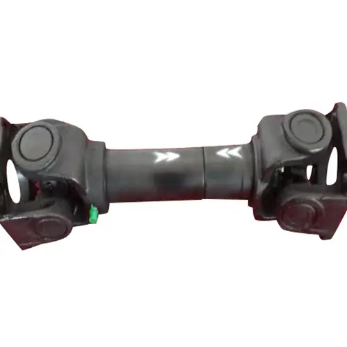
Spline PTO Shaft Cardan Splined Shape Tractor Flexible Drive Shaft for Agricultural Machines
Product Description
The Spline PTO Shaft Cardan Splined Shape Tractor Flexible Drive Shaft for agricultural machinery is an indispensable component for efficient power transmission. Engineered with precision, it ensures optimal performance and durability under various farming conditions.
1. Product Details
| Model Number | 77268L/77272L/78869/U356 |
| Function | Power Transmission |
| Use | Tractors and Various Farm Implements |
| Place of Origin | Hangzhou, Zhejiang, China (Mainland) |
| Brand Name | DCT MACHINARY |
| Yoke Type | Push Pin/Quick Release/Collar/Double Push Pin/Bolt Pins/Split Pins |
| Processing of Yoke | Forging |
| Plastic Cover | YW; BW; YS; BS |
| Color | Yellow; Black |
| Series | T Series; L Series; S Series |
| Tube Type | Triangular/Star/Lemon |
| Processing of Tube | Cold Drawn |
| Spline Type | 1 3/8″ Z6; 1 3/8 Z21; 1 3/4 Z20; 1 1/8 Z6; 1 3/4 Z6 |
2. More Products
Explore our extensive range of high-quality drive shafts, each meticulously designed to meet the diverse needs of modern agriculture.
3. The Structure of PTO Shaft
The PTO shaft is constructed from robust materials, ensuring durability and reliability. Its innovative design facilitates smooth power transmission, making it a vital component for agricultural machinery.
4. Installing Process
Installation is streamlined and user-friendly. Follow the provided guidelines to ensure proper setup and operation, maximizing the efficiency of your agricultural equipment.
5. Packing and Shipping
Products are securely packaged to prevent damage during transit. We offer timely shipping services to ensure that your orders reach you promptly.
Other Product Offerings
EVER-POWER GROUP specializes in various industrial products, including agricultural gearboxes, power output shafts, sprockets, fluid couplings, worm gear reducers, gears and racks, roller chains, pulleys, planetary gearboxes, timing pulleys, and bushings. We pride ourselves on high-quality products, competitive prices, and exceptional customer service. Custom drawings and samples are welcome. Explore our extensive catalog and find the perfect solution for your industrial needs.
FAQs
1. Are your products forged or cast?
All of our products are forged.
2. What’s your MOQ?
20 PCS for each type. We accept sample orders.
3. What’s the horsepower range for the PTO shafts?
We provide a full range of PTO shafts, ranging from 16HP to 200HP.
4. How many spline specifications do you offer?
We produce 1 1/8″-Z6, 1 3/8″-Z6, 1 3/4″-Z6, 1 3/8″-Z21, 1 3/4″-Z20, 8X42X48X8, and 8X32X38X6 splines.
5. What is your warranty policy?
We offer a 1-year warranty. In case of quality issues, we will send new products free of charge with the next shipment.
All the content of the page is from the Internet, the content is only as a reference for product selection, our products are replacement parts and not original spare parts; we are not the holder of the original trademarks of the content, our products are only suitable for after-sales replacement parts and not original spare parts, our replacement parts can be perfectly adapted to the original spare parts; if you need to buy original spare parts, please contact the original factory to buy. If you want to buy original spare parts, please contact the original supplier for purchase.
Performance Characteristics of Cardan Shaft
The Cardan shaft is an essential component in various mechanical systems. Here are its key performance characteristics:
- High Torque Transmission: The Cardan shaft can transmit high levels of torque, which is crucial for heavy-duty applications.
- Flexibility: It offers significant flexibility, accommodating misalignments in the mechanical system without compromising performance.
- Durability: Made from robust materials, the Cardan shaft exhibits excellent resistance to wear and tear, ensuring long service life.
- Vibration Dampening: Its design helps in reducing vibrations, leading to smoother operation of the machinery.
Types and Characteristics of Cardan Shaft
There are several types of Cardan shafts available, each designed for specific applications:
- Single Cardan Shaft: Simple and cost-effective, suitable for applications with minimal misalignment.
- Double Cardan Shaft: Provides better performance in terms of reducing vibrations and accommodating greater misalignments.
- Constant Velocity (CV) Shaft: Ideal for high-speed applications, offering consistent rotational speeds without significant vibration.
The materials used in manufacturing Cardan shafts also play a crucial role:
- Steel: Most commonly used, offering excellent strength and durability.
- Aluminum: Lighter than steel, providing improved fuel efficiency in automotive applications.
- Composite Materials: These offer a balance of strength and weight reduction, ideal for aerospace applications.
Application of Cardan Shaft in Various Industries
The Cardan shaft finds applications across different industries due to its versatile characteristics:
- Automotive Industry: Used extensively in drivetrain systems to transmit torque from the engine to the wheels.
- Aerospace Industry: Essential in control systems for helicopters and other aircraft, providing reliable power transmission.
- Marine Industry: Vital for the propulsion systems in ships and boats, ensuring efficient power transfer.
- Industrial Machinery: Helps in the smooth operation of heavy machinery and manufacturing equipment.
- Agricultural Equipment: Used in tractors and other farming machinery for effective power distribution.
Future Development Trends and Opportunities of Cardan Shaft Products
The future of Cardan shaft products is promising, with several trends and opportunities emerging:
- Advanced Materials: The development of new materials will enhance the performance and reduce the weight of Cardan shafts.
- Improved Manufacturing Techniques: Advances in manufacturing processes will lead to more precise and efficient production of Cardan shafts.
- Integration of Smart Technologies: Incorporating sensors and smart technology will allow for real-time monitoring and maintenance.
- Growth in Electric Vehicles: The rise of electric vehicles presents new opportunities for Cardan shaft applications in innovative drivetrain systems.
These trends indicate a bright future for Cardan shaft products, with continuous improvements and expanding applications.
How to Choose a Suitable Cardan Shaft
Choosing the right Cardan shaft involves careful consideration of several factors:
- Determine Application Requirements: Understand the specific needs of your application, including the type of machinery and expected performance.
- Evaluating Power Requirements: Ensure the shaft can handle the power output of the machinery.
- Check Speed and Torque Specifications: Verify that the shaft can operate within the required speed and torque limits.
- Measuring the Length of the Shaft: Accurate measurements are crucial for proper fit and function.
- Evaluate Connection Type: Ensure the shaft’s connections are compatible with your machinery.
- Check Safety Features: Consider the safety mechanisms in place to prevent failures and ensure safe operation.
Conclusion
The Cardan shaft is a critical component in many mechanical systems, offering high torque transmission, flexibility, and durability. Its applications span across various industries, including automotive, aerospace, marine, industrial machinery, and agricultural equipment. The future development trends and opportunities for Cardan shaft products are promising, with advancements in materials, manufacturing techniques, and smart technologies. By carefully considering application requirements, power needs, speed and torque specifications, shaft length, connection types, and safety features, one can select the most suitable Cardan shaft for their needs.
Author: Dream
China best Professional Drive Shaft Cardan Shaft with High Performance for Rolling Mill 12v air compressor
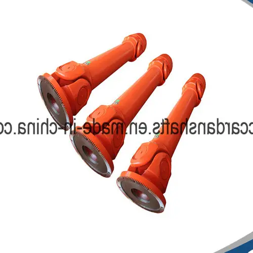
High-Performance Drive Shaft Cardan Shaft for Rolling Mill Applications
Product Description
The high-performance drive shaft, also known as a Cardan shaft, is engineered specifically for rolling mill applications. Renowned for its ISO certification, this professional-grade shaft ensures optimal functionality and durability.
Specifications
| Structure | Universal | Flexible or Rigid | Rigid | Standard or Nonstandard | Nonstandard |
| Material | Alloy steel | Brand name | HangZhou XIHU (WEST LAKE) DIS. | Place of origin | ZheJiang, China |
| Model | SWC Medium | Raw materials | Heat treatment | Length | Depend on specification |
| Flange DIA | 160mm~620mm | Nominal torque | Depend on required specification (please confirm with us) | Coating | Heavy duty industrial paint |
| Paint color | Customization | Application | Rolling mill machinery | OEM/ODM | Available |
| Certification | ISO, TUV, SGS | Price | Calculate according to required specification | Custom service | Available |
Packaging & Delivery
Packaging details: Standard plywood case
Delivery detail: 15-20 working days, depending on the actual production condition
Other Product Offerings
EVER-POWER GROUP is a premier supplier of various industrial products. Our offerings include agricultural gearboxes, power output shafts, sprockets, fluid couplings, worm gear reducers, gears and racks, roller chains, pulleys and pulleys, planetary gearboxes, timing pulleys, and bushings. We pride ourselves on providing high-quality products at competitive prices, coupled with impeccable services. Customers are welcome to customize their orders with drawings and samples to meet specific requirements.
FAQs
Q1: What is the material used for the drive shaft?
A1: The drive shaft is made from high-quality alloy steel, ensuring durability and high performance.
Q2: Can the drive shaft be customized?
A2: Yes, customization options are available for paint color, specifications, and other requirements.
Q3: What certifications does the drive shaft have?
A3: The drive shaft comes with ISO, TUV, and SGS certifications.
Q4: How is the product packaged for delivery?
A4: The product is packaged in a standard plywood case to ensure safe transportation.
Q5: What is the typical delivery time for the drive shaft?
A5: The typical delivery time is 15-20 working days, depending on the actual production condition.
All the content of the page is from the Internet, the content is only as a reference for product selection, our products are replacement parts and not original spare parts; we are not the holder of the original trademarks of the content, our products are only suitable for after-sales replacement parts and not original spare parts, our replacement parts can be perfectly adapted to the original spare parts; if you need to buy original spare parts, please contact the original factory to buy. If you want to buy original spare parts, please contact the original supplier for purchase.
Performance Characteristics of Cardan Shaft
The Cardan shaft is an essential component in various mechanical systems. Here are its key performance characteristics:
- High Torque Transmission: The Cardan shaft can transmit high levels of torque, which is crucial for heavy-duty applications.
- Flexibility: It offers significant flexibility, accommodating misalignments in the mechanical system without compromising performance.
- Durability: Made from robust materials, the Cardan shaft exhibits excellent resistance to wear and tear, ensuring long service life.
- Vibration Dampening: Its design helps in reducing vibrations, leading to smoother operation of the machinery.
Types and Characteristics of Cardan Shaft
There are several types of Cardan shafts available, each designed for specific applications:
- Single Cardan Shaft: Simple and cost-effective, suitable for applications with minimal misalignment.
- Double Cardan Shaft: Provides better performance in terms of reducing vibrations and accommodating greater misalignments.
- Constant Velocity (CV) Shaft: Ideal for high-speed applications, offering consistent rotational speeds without significant vibration.
The materials used in manufacturing Cardan shafts also play a crucial role:
- Steel: Most commonly used, offering excellent strength and durability.
- Aluminum: Lighter than steel, providing improved fuel efficiency in automotive applications.
- Composite Materials: These offer a balance of strength and weight reduction, ideal for aerospace applications.
Application of Cardan Shaft in Various Industries
The Cardan shaft finds applications across different industries due to its versatile characteristics:
- Automotive Industry: Used extensively in drivetrain systems to transmit torque from the engine to the wheels.
- Aerospace Industry: Essential in control systems for helicopters and other aircraft, providing reliable power transmission.
- Marine Industry: Vital for the propulsion systems in ships and boats, ensuring efficient power transfer.
- Industrial Machinery: Helps in the smooth operation of heavy machinery and manufacturing equipment.
- Agricultural Equipment: Used in tractors and other farming machinery for effective power distribution.
Future Development Trends and Opportunities of Cardan Shaft Products
The future of Cardan shaft products is promising, with several trends and opportunities emerging:
- Advanced Materials: The development of new materials will enhance the performance and reduce the weight of Cardan shafts.
- Improved Manufacturing Techniques: Advances in manufacturing processes will lead to more precise and efficient production of Cardan shafts.
- Integration of Smart Technologies: Incorporating sensors and smart technology will allow for real-time monitoring and maintenance.
- Growth in Electric Vehicles: The rise of electric vehicles presents new opportunities for Cardan shaft applications in innovative drivetrain systems.
These trends indicate a bright future for Cardan shaft products, with continuous improvements and expanding applications.
How to Choose a Suitable Cardan Shaft
Choosing the right Cardan shaft involves careful consideration of several factors:
- Determine Application Requirements: Understand the specific needs of your application, including the type of machinery and expected performance.
- Evaluating Power Requirements: Ensure the shaft can handle the power output of the machinery.
- Check Speed and Torque Specifications: Verify that the shaft can operate within the required speed and torque limits.
- Measuring the Length of the Shaft: Accurate measurements are crucial for proper fit and function.
- Evaluate Connection Type: Ensure the shaft’s connections are compatible with your machinery.
- Check Safety Features: Consider the safety mechanisms in place to prevent failures and ensure safe operation.
Conclusion
The Cardan shaft is a critical component in many mechanical systems, offering high torque transmission, flexibility, and durability. Its applications span across various industries, including automotive, aerospace, marine, industrial machinery, and agricultural equipment. The future development trends and opportunities for Cardan shaft products are promising, with advancements in materials, manufacturing techniques, and smart technologies. By carefully considering application requirements, power needs, speed and torque specifications, shaft length, connection types, and safety features, one can select the most suitable Cardan shaft for their needs.
Author: Dream
China best Wide Angle Pto Adaptor Cardan Spline Shaft Yoke Tube Torque Limiter Universal Joint Cross Cover Agricultural Machinery Tractor Parts Pto Drive Shaft air compressor repair near me
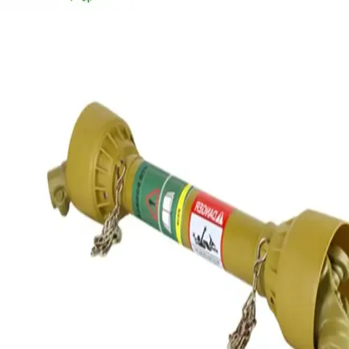
Wide Angle PTO Adaptor Cardan Spline Shaft for Agricultural Machinery
Product Description
A PTO shaft (Power Take-Off shaft) is an essential mechanical component that facilitates power transfer from a tractor or another power source to an attached implement such as a mower, tiller, or baler. This mighty shaft is typically positioned at the rear of the tractor, drawing power from the engine through the transmission.
The PTO shaft is meticulously designed to deliver a rotating power source to the implement, enabling it to execute its intended functions seamlessly. The implement connects to the PTO shaft via a universal joint, which accommodates movement between the tractor and the implement while maintaining a steady power transfer.
Advantages of Our PTO Shafts
- Robust Construction: Our forged yokes ensure that the PTO shafts possess the strength required for rigorous usage and operation.
- Precision Fit: Internal dimensions are standardized to guarantee smooth and hassle-free installation.
- Certified Quality: Our products are backed by CE and ISO certifications, affirming their superior quality.
- Secure Packaging: Professional and sturdy packaging ensures that the goods remain in pristine condition upon delivery.
Product Specifications
| SHIELD S | SHIELD W |
|---|---|
Packaging & Shipping
We provide robust and professional packaging solutions to ensure the safe arrival of your products. Shipping methods are flexible to meet your needs, with sea transport being the most common delivery method.
Other Product Offerings
In addition to top-quality PTO shafts, EVER-POWER GROUP offers an extensive range of products for various industrial applications. Our portfolio includes agricultural gearboxes, power output shafts, sprockets, fluid couplings, worm gear reducers, gears and racks, roller chains, pulleys and pulleys, planetary gearboxes, timing pulleys, and bushings. We pride ourselves on providing high-quality products at competitive prices, supported by excellent customer service. We welcome custom orders based on drawings and samples.
FAQ
1. What are your main products?
Our primary products include PTO shafts, gearboxes, hydraulic parts like cylinders, valves, gear pumps, and motors. Detailed specifications are available on our website, and you can email us for recommendations based on your requirements.
2. What is the lead time for a regular order?
Typically, our standard products have a lead time of 30-45 days. Customized products may take longer. However, we are flexible and can adjust based on specific orders.
3. What are your warranty terms?
We offer a one-year warranty on all our products.
4. Can you provide a price list?
Due to the customized nature of our products, it is challenging to provide a standard price list. Prices vary based on requirements like length, ratio, voltage, power, and annual quantity. Please share your details, and we will provide a tailored offer.
5. How do you deliver the goods?
We typically ship goods by sea. Other arrangements can be made based on customer requirements.
All the content of the page is from the Internet, the content is only as a reference for product selection, our products are replacement parts and not original spare parts; we are not the holder of the original trademarks of the content, our products are only suitable for after-sales replacement parts and not original spare parts, our replacement parts can be perfectly adapted to the original spare parts; if you need to buy original spare parts, please contact the original factory to buy. If you want to buy original spare parts, please contact the original supplier for purchase.
Performance Characteristics of Cardan Shaft
The Cardan shaft is an essential component in various mechanical systems. Here are its key performance characteristics:
- High Torque Transmission: The Cardan shaft can transmit high levels of torque, which is crucial for heavy-duty applications.
- Flexibility: It offers significant flexibility, accommodating misalignments in the mechanical system without compromising performance.
- Durability: Made from robust materials, the Cardan shaft exhibits excellent resistance to wear and tear, ensuring long service life.
- Vibration Dampening: Its design helps in reducing vibrations, leading to smoother operation of the machinery.
Types and Characteristics of Cardan Shaft
There are several types of Cardan shafts available, each designed for specific applications:
- Single Cardan Shaft: Simple and cost-effective, suitable for applications with minimal misalignment.
- Double Cardan Shaft: Provides better performance in terms of reducing vibrations and accommodating greater misalignments.
- Constant Velocity (CV) Shaft: Ideal for high-speed applications, offering consistent rotational speeds without significant vibration.
The materials used in manufacturing Cardan shafts also play a crucial role:
- Steel: Most commonly used, offering excellent strength and durability.
- Aluminum: Lighter than steel, providing improved fuel efficiency in automotive applications.
- Composite Materials: These offer a balance of strength and weight reduction, ideal for aerospace applications.
Application of Cardan Shaft in Various Industries
The Cardan shaft finds applications across different industries due to its versatile characteristics:
- Automotive Industry: Used extensively in drivetrain systems to transmit torque from the engine to the wheels.
- Aerospace Industry: Essential in control systems for helicopters and other aircraft, providing reliable power transmission.
- Marine Industry: Vital for the propulsion systems in ships and boats, ensuring efficient power transfer.
- Industrial Machinery: Helps in the smooth operation of heavy machinery and manufacturing equipment.
- Agricultural Equipment: Used in tractors and other farming machinery for effective power distribution.
Future Development Trends and Opportunities of Cardan Shaft Products
The future of Cardan shaft products is promising, with several trends and opportunities emerging:
- Advanced Materials: The development of new materials will enhance the performance and reduce the weight of Cardan shafts.
- Improved Manufacturing Techniques: Advances in manufacturing processes will lead to more precise and efficient production of Cardan shafts.
- Integration of Smart Technologies: Incorporating sensors and smart technology will allow for real-time monitoring and maintenance.
- Growth in Electric Vehicles: The rise of electric vehicles presents new opportunities for Cardan shaft applications in innovative drivetrain systems.
These trends indicate a bright future for Cardan shaft products, with continuous improvements and expanding applications.
How to Choose a Suitable Cardan Shaft
Choosing the right Cardan shaft involves careful consideration of several factors:
- Determine Application Requirements: Understand the specific needs of your application, including the type of machinery and expected performance.
- Evaluating Power Requirements: Ensure the shaft can handle the power output of the machinery.
- Check Speed and Torque Specifications: Verify that the shaft can operate within the required speed and torque limits.
- Measuring the Length of the Shaft: Accurate measurements are crucial for proper fit and function.
- Evaluate Connection Type: Ensure the shaft’s connections are compatible with your machinery.
- Check Safety Features: Consider the safety mechanisms in place to prevent failures and ensure safe operation.
Conclusion
The Cardan shaft is a critical component in many mechanical systems, offering high torque transmission, flexibility, and durability. Its applications span across various industries, including automotive, aerospace, marine, industrial machinery, and agricultural equipment. The future development trends and opportunities for Cardan shaft products are promising, with advancements in materials, manufacturing techniques, and smart technologies. By carefully considering application requirements, power needs, speed and torque specifications, shaft length, connection types, and safety features, one can select the most suitable Cardan shaft for their needs.
Author: Dream