Product Description
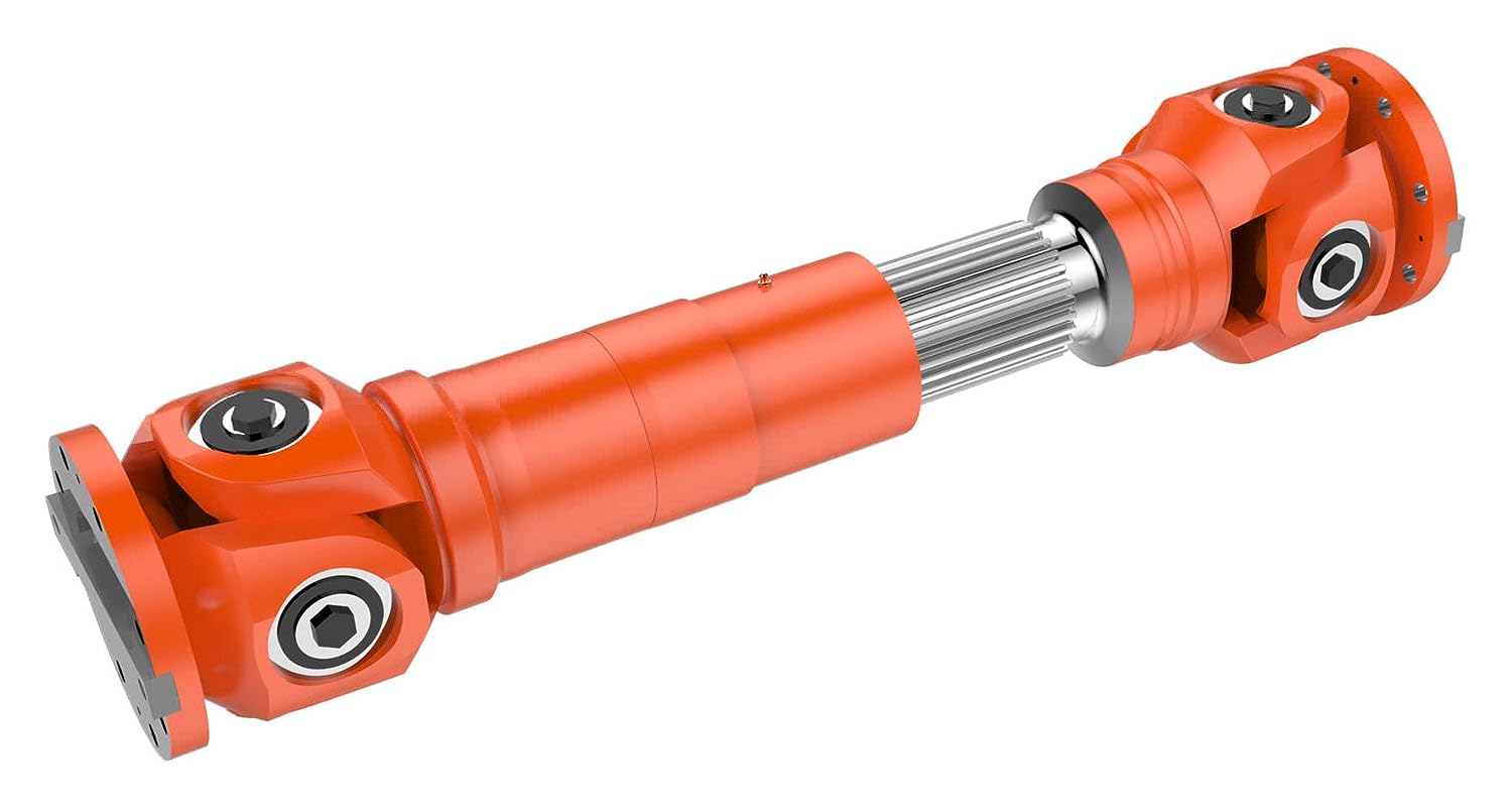
SWC-WF Type Non-Stretch Flange Universal Joint Shaft Coupling/Cardan Shaft
Description:
The SWC-WF non flexible flange type universal joint is a Universal joint with 2 bent joints. This enables it to work at an angle of up to 90 degrees. It is a non flexible flange type, which means there is no flexible coupling between 2 bent joints. This makes it harder and more suitable for applications with significant vibrations or impacts.
The SWC-WF non flexible flange type universal joint is the most commonly used universal joint, and its structural feature is that it cannot reliably transmit torque and motion at the same axis or axis angle or 2 large equiangular continuous rotational speeds with large axial motion. It can be widely used for torque transmission in heavy machinery industries such as metallurgy, lifting, transportation, mining, petroleum, shipbuilding, coal, rubber, papermaking machinery, etc. Overall, the SWC-WF non flexible flange universal coupling is a high-quality and reliable product that is very suitable for various applications. It is more expensive than other types of universal joints, but it provides many advantages, such as being able to work at angles below 90 degrees and being durable.
Advantages:
1. Flexibility: SWC-WF does not come with a flexible flange type universal coupling and can transmit power between 2 shafts with angles up to 90 degrees. This makes it very suitable for applications with high misalignment, such as in mobile machinery or agricultural equipment.
2. Durability: The SWC-WF non flexible flange universal coupling is made of high-quality materials and designed to withstand harsh environments. It is also equipped with a set of bearings to help reduce friction and vibration, thereby extending the service life of the coupling.
3. Easy to maintain: The SWC-WF non flexible flange universal coupling is easy to install and maintain. The bearings are easy to access and can be replaced if necessary.
4. Double joint design: The double joint design allows SWC-WF to transmit power between 2 shafts with angles up to 90 degrees without a flexible flange type universal coupling. This makes it very suitable for applications with high misalignment.
5. Cost effectiveness: The SWC-WF non flexible flange universal coupling is a cost-effective solution suitable for applications that require high flexibility and durability.
Overall, the SWC-WF non flexible flange type universal joint is a universal and reliable coupling that has many advantages compared to other types of universal joints. For applications that require high flexibility, durability, and ease of maintenance, it is a good choice.
Product parameters:
Packing & shipping:
1 Prevent from damage.
2. As customers’ requirements, in perfect condition.
3. Delivery : As per contract delivery on time
4. Shipping : As per client request. We can accept CIF, Door to Door etc. or client authorized agent we supply all the necessary assistant.
FAQ:
Q 1: Are you a trading company or a manufacturer?
A: We are a professional manufacturer specializing in manufacturing various series of couplings.
Q 2:Can you do OEM?
Yes, we can. We can do OEM & ODM for all the customers with customized artworks in PDF or AI format.
Q 3:How long is your delivery time?
Generally, it is 20-30 days if the goods are not in stock. It is according to quantity.
Q 4: How long is your warranty?
A: Our Warranty is 12 months under normal circumstances.
Q 5: Do you have inspection procedures for coupling?
A:100% self-inspection before packing.
Q 6: Can I have a visit to your factory before the order?
A: Sure, welcome to visit our factory.
/* January 22, 2571 19:08:37 */!function(){function s(e,r){var a,o={};try{e&&e.split(“,”).forEach(function(e,t){e&&(a=e.match(/(.*?):(.*)$/))&&1
| Standard Or Nonstandard: | Standard |
|---|---|
| Shaft Hole: | 19-32 |
| Torque: | >80N.M |
| Bore Diameter: | 19mm |
| Speed: | 4000r/M |
| Structure: | Flexible |
| Customization: |
Available
| Customized Request |
|---|
How do manufacturers ensure the compatibility of cardan shafts with different equipment?
Manufacturers take several measures to ensure the compatibility of cardan shafts with different equipment. These measures involve careful design, engineering, and manufacturing processes to meet the specific requirements of diverse applications. Let’s explore how manufacturers ensure compatibility:
1. Application Analysis:
– Manufacturers begin by analyzing the application requirements and specifications provided by customers. This analysis includes understanding factors such as torque, speed, misalignment, operating conditions, space limitations, and other specific needs. By evaluating these parameters, manufacturers can determine the appropriate design and configuration of the cardan shaft to ensure compatibility with the equipment.
2. Customization Options:
– Manufacturers offer customization options for cardan shafts to meet the unique requirements of different equipment. This includes providing various lengths, sizes, torque capacities, connection methods, and material options. Customers can work closely with manufacturers to select or design a cardan shaft that fits their specific equipment and ensures compatibility with the system’s power transmission needs.
3. Engineering Expertise:
– Manufacturers employ experienced engineers who specialize in cardan shaft design and engineering. These experts have in-depth knowledge of mechanical power transmission and understand the complexities involved in ensuring compatibility. They use their expertise to design cardan shafts that can handle the specific torque, speed, misalignment, and other parameters required by different equipment.
4. Computer-Aided Design (CAD) and Simulation:
– Manufacturers utilize advanced computer-aided design (CAD) software and simulation tools to model and simulate the behavior of cardan shafts in different equipment scenarios. These tools allow engineers to analyze the stress distribution, bearing performance, and other critical factors to ensure the shaft’s compatibility and performance. By simulating the cardan shaft’s behavior under various loading conditions, manufacturers can optimize its design and validate its compatibility.
5. Quality Control and Testing:
– Manufacturers have stringent quality control processes in place to ensure the reliability, durability, and compatibility of cardan shafts. They conduct thorough testing to verify the performance and functionality of the shafts in real-world conditions. This may involve testing for torque capacity, speed limits, vibration resistance, misalignment tolerance, and other relevant parameters. By subjecting the cardan shafts to rigorous testing, manufacturers can ensure their compatibility with different equipment and validate their ability to deliver reliable power transmission.
6. Adherence to Standards and Regulations:
– Manufacturers follow industry standards and regulations when designing and manufacturing cardan shafts. Compliance with these standards ensures that the shafts meet the necessary safety, performance, and compatibility requirements. Examples of such standards include ISO 9001 for quality management and ISO 14001 for environmental management. By adhering to these standards, manufacturers demonstrate their commitment to producing compatible and high-quality cardan shafts.
7. Collaboration with Customers:
– Manufacturers actively collaborate with customers to understand their equipment and system requirements. They engage in discussions, provide technical support, and offer guidance to ensure the compatibility of the cardan shafts. By fostering a collaborative relationship, manufacturers can address specific challenges and tailor the design and specifications of the shaft to meet the unique requirements of different equipment.
In summary, manufacturers ensure the compatibility of cardan shafts with different equipment through application analysis, customization options, engineering expertise, CAD and simulation tools, quality control and testing, adherence to standards, and collaboration with customers. These measures allow manufacturers to design and produce cardan shafts that meet the specific torque, speed, misalignment, and other requirements of various equipment, ensuring optimal compatibility and efficient power transmission.

How do cardan shafts handle variations in load, speed, and misalignment during operation?
Cardan shafts are designed to handle variations in load, speed, and misalignment during operation. They incorporate specific features and mechanisms to accommodate these factors and ensure efficient power transmission. Let’s explore how cardan shafts handle these variations:
1. Load Variation:
– Cardan shafts are designed to transmit torque and handle variations in load. The torque capacity of the shaft is determined based on the application’s requirements, and the shaft is manufactured using materials and dimensions that can withstand the specified loads. The design and construction of the shaft, including the selection of universal joints and slip yokes, are optimized to handle the anticipated loads. By choosing appropriate material strengths and dimensions, cardan shafts can effectively transmit varying loads without failure or excessive deflection.
2. Speed Variation:
– Cardan shafts can accommodate variations in rotational speed between the driving and driven components. The universal joints, which connect the shaft’s segments, allow for angular movement, thereby compensating for speed differences. The design of the universal joints and the use of needle bearings or roller bearings enable smooth rotation and efficient power transmission even at varying speeds. However, it’s important to note that excessively high speeds can introduce additional challenges such as increased vibration and wear, which may require additional measures such as balancing and lubrication.
3. Misalignment Compensation:
– Cardan shafts are specifically designed to handle misalignment between the driving and driven components. They can accommodate angular misalignment, parallel offset, and axial displacement to a certain extent. The universal joints in the shaft assembly allow for flexibility and articulation, enabling the shaft to transmit torque even when the components are not perfectly aligned. The design of the universal joints, along with their bearing arrangements and seals, allows for smooth rotation and compensation of misalignment. Manufacturers specify the maximum allowable misalignment angles and displacements for cardan shafts, and exceeding these limits can lead to increased wear, vibration, and reduced efficiency.
4. Telescopic Design:
– Cardan shafts often feature a telescopic design, which allows for axial movement and adjustment to accommodate variations in distance between the driving and driven components. This telescopic design enables the shaft to handle changes in length during operation, such as when the vehicle or equipment undergoes suspension movement or when the drivetrain components experience positional changes. The telescopic mechanism ensures that the shaft remains properly connected and engaged, maintaining power transmission efficiency even when there are fluctuations in distance or position.
5. Regular Maintenance:
– To ensure optimal performance and longevity, cardan shafts require regular maintenance. This includes inspections, lubrication of universal joints and slip yokes, and monitoring for wear or damage. Regular maintenance helps identify and address any issues related to load, speed, or misalignment variations, ensuring that the shaft continues to function effectively under changing operating conditions.
Overall, cardan shafts handle variations in load, speed, and misalignment through their design features such as universal joints, telescopic design, and flexibility. By incorporating these elements, along with proper material selection, lubrication, and maintenance practices, cardan shafts can reliably transmit torque and accommodate the changing operating conditions in vehicles and equipment.
What is a cardan shaft and how does it function in vehicles and machinery?
A cardan shaft, also known as a propeller shaft or drive shaft, is a mechanical component used in vehicles and machinery to transmit torque and rotational power between two points that are not in line with each other. It consists of a tubular shaft with universal joints at each end, allowing for flexibility and accommodating misalignment between the driving and driven components. The cardan shaft plays a crucial role in transferring power from the engine or power source to the wheels or driven machinery. Here’s how it functions in vehicles and machinery:
1. Torque Transmission:
– In vehicles, the cardan shaft connects the transmission or gearbox to the differential, which then distributes torque to the wheels. When the engine generates rotational power, it is transmitted through the transmission to the cardan shaft. The universal joints at each end of the shaft allow for angular misalignment and compensate for variations in the suspension, axle movement, and road conditions. As the cardan shaft rotates, it transfers torque from the transmission to the differential, enabling power delivery to the wheels.
– In machinery, the cardan shaft serves a similar purpose of transmitting torque between the power source and driven components. For example, in agricultural equipment, the cardan shaft connects the tractor’s PTO (Power Take-Off) to various implements such as mowers, balers, or tillers. The rotational power from the tractor’s engine is transferred through the PTO driveline to the cardan shaft, which then transmits the torque to the driven machinery, enabling their operation.
2. Flexibility and Compensation:
– The cardan shaft’s design with universal joints provides flexibility and compensates for misalignment between the driving and driven components. The universal joints allow the shaft to bend and articulate while maintaining a continuous torque transmission. This flexibility is essential in vehicles and machinery where the driving and driven components may be at different angles or positions due to suspension movement, axle articulation, or uneven terrain. The cardan shaft absorbs these variations and ensures smooth power delivery without causing excessive stress or vibration.
3. Balancing and Vibration Control:
– Cardan shafts also contribute to balancing and vibration control in vehicles and machinery. The rotation of the shaft generates centrifugal forces, and any imbalance can result in vibration and reduced performance. To counterbalance this, cardan shafts are carefully designed and balanced to minimize vibration and provide smooth operation. Additionally, the universal joints help in absorbing minor vibrations and reducing their transmission to the vehicle or machinery.
4. Length Adjustment:
– Cardan shafts offer the advantage of adjustable length, allowing for variations in the distance between the driving and driven components. This adjustability is particularly useful in vehicles and machinery with adjustable wheelbases or variable attachment points. By adjusting the length of the cardan shaft, the driveline can be appropriately sized and positioned to accommodate different configurations, ensuring optimal power transmission efficiency.
5. Safety Features:
– Cardan shafts in vehicles and machinery often incorporate safety features to protect against mechanical failures. These may include shielding or guards to prevent contact with rotating components, such as the driveshaft or universal joints. In the event of a joint failure or excessive force, some cardan shafts may also incorporate shear pins or torque limiters to prevent damage to the driveline and protect other components from excessive loads.
In summary, a cardan shaft is a tubular component with universal joints at each end used to transmit torque and rotational power between non-aligned driving and driven components. It provides flexibility, compensates for misalignment, and enables torque transmission in vehicles and machinery. By efficiently transferring power, accommodating variations, and balancing vibrations, cardan shafts play a critical role in ensuring smooth and reliable operation in a wide range of applications.


editor by CX 2024-04-19
China OEM SWC-Wf Type Non-Stretch Flange Universal Joint Shaft Coupling/Cardan Shaft
Product Description
SWC-WF Type Non-Stretch Flange Universal Joint Shaft Coupling/Cardan Shaft
Description:
The SWC-WF non flexible flange type universal joint is a Universal joint with 2 bent joints. This enables it to work at an angle of up to 90 degrees. It is a non flexible flange type, which means there is no flexible coupling between 2 bent joints. This makes it harder and more suitable for applications with significant vibrations or impacts.
The SWC-WF non flexible flange type universal joint is the most commonly used universal joint, and its structural feature is that it cannot reliably transmit torque and motion at the same axis or axis angle or 2 large equiangular continuous rotational speeds with large axial motion. It can be widely used for torque transmission in heavy machinery industries such as metallurgy, lifting, transportation, mining, petroleum, shipbuilding, coal, rubber, papermaking machinery, etc. Overall, the SWC-WF non flexible flange universal coupling is a high-quality and reliable product that is very suitable for various applications. It is more expensive than other types of universal joints, but it provides many advantages, such as being able to work at angles below 90 degrees and being durable.
Advantages:
1. Flexibility: SWC-WF does not come with a flexible flange type universal coupling and can transmit power between 2 shafts with angles up to 90 degrees. This makes it very suitable for applications with high misalignment, such as in mobile machinery or agricultural equipment.
2. Durability: The SWC-WF non flexible flange universal coupling is made of high-quality materials and designed to withstand harsh environments. It is also equipped with a set of bearings to help reduce friction and vibration, thereby extending the service life of the coupling.
3. Easy to maintain: The SWC-WF non flexible flange universal coupling is easy to install and maintain. The bearings are easy to access and can be replaced if necessary.
4. Double joint design: The double joint design allows SWC-WF to transmit power between 2 shafts with angles up to 90 degrees without a flexible flange type universal coupling. This makes it very suitable for applications with high misalignment.
5. Cost effectiveness: The SWC-WF non flexible flange universal coupling is a cost-effective solution suitable for applications that require high flexibility and durability.
Overall, the SWC-WF non flexible flange type universal joint is a universal and reliable coupling that has many advantages compared to other types of universal joints. For applications that require high flexibility, durability, and ease of maintenance, it is a good choice.
Product parameters:
Packing & shipping:
1 Prevent from damage.
2. As customers’ requirements, in perfect condition.
3. Delivery : As per contract delivery on time
4. Shipping : As per client request. We can accept CIF, Door to Door etc. or client authorized agent we supply all the necessary assistant.
FAQ:
Q 1: Are you a trading company or a manufacturer?
A: We are a professional manufacturer specializing in manufacturing various series of couplings.
Q 2:Can you do OEM?
Yes, we can. We can do OEM & ODM for all the customers with customized artworks in PDF or AI format.
Q 3:How long is your delivery time?
Generally, it is 20-30 days if the goods are not in stock. It is according to quantity.
Q 4: How long is your warranty?
A: Our Warranty is 12 months under normal circumstances.
Q 5: Do you have inspection procedures for coupling?
A:100% self-inspection before packing.
Q 6: Can I have a visit to your factory before the order?
A: Sure, welcome to visit our factory.
/* January 22, 2571 19:08:37 */!function(){function s(e,r){var a,o={};try{e&&e.split(“,”).forEach(function(e,t){e&&(a=e.match(/(.*?):(.*)$/))&&1
| Standard Or Nonstandard: | Standard |
|---|---|
| Shaft Hole: | 19-32 |
| Torque: | >80N.M |
| Bore Diameter: | 19mm |
| Speed: | 4000r/M |
| Structure: | Flexible |
| Customization: |
Available
| Customized Request |
|---|

Are there any limitations or disadvantages associated with cardan shaft systems?
While cardan shaft systems offer numerous advantages, they also have some limitations and disadvantages that should be considered. Let’s explore these limitations in detail:
1. Angular Misalignment:
– Cardan shafts are designed to accommodate angular misalignment between the driving and driven components. However, excessive misalignment can lead to increased wear, vibration, and decreased efficiency. If the misalignment exceeds the recommended limits, it can put additional stress on the universal joints and other components, reducing the lifespan of the shaft and potentially causing mechanical failures.
2. Noise and Vibration:
– Cardan shaft systems can introduce noise and vibration into the equipment or vehicle. The universal joints and slip yokes in the shaft assembly can generate vibrations as they rotate, especially at high speeds. These vibrations can contribute to increased noise levels, potentially causing discomfort for passengers or affecting the performance of sensitive equipment. Proper balancing and maintenance of the shaft can help mitigate these effects, but they may still be present to some extent.
3. Maintenance and Lubrication:
– Cardan shaft systems require regular maintenance and lubrication to ensure optimal performance and longevity. The universal joints and slip yokes need to be properly lubricated to minimize friction and wear. If maintenance is neglected, the joints can wear out quickly, leading to increased vibration, noise, and potential failure. Regular inspections and lubrication are necessary to maintain the efficiency and reliability of cardan shaft systems.
4. Limited Flexibility in High-Speed Applications:
– Cardan shafts have limitations when it comes to high-speed applications. At high rotational speeds, the centrifugal forces acting on the rotating components can cause significant stress on the shaft and universal joints. This can result in increased wear, reduced lifespan, and potential failure. In such cases, alternative power transmission systems such as constant-velocity (CV) joints or direct drives may be more suitable.
5. Space and Weight Constraints:
– Cardan shaft systems require sufficient space for installation due to their length and telescopic design. In applications with limited space constraints, it may be challenging to accommodate the full length of the shaft, or modifications may be necessary to ensure proper fit. Additionally, the weight of the shaft can be a consideration, especially in applications where weight reduction is crucial. In such cases, alternative lightweight materials or drive systems may be more appropriate.
6. Cost:
– Cardan shaft systems can be relatively costly compared to other power transmission options. The complexity of their design, the need for customization, and the use of multiple components contribute to higher manufacturing and installation costs. However, it’s important to consider the overall benefits and performance of cardan shaft systems when evaluating their cost-effectiveness for specific applications.
7. Limited Misalignment Compensation:
– While cardan shafts can accommodate angular misalignment, they have limitations when it comes to compensating for other types of misalignment, such as parallel offset or axial displacement. In applications that require significant compensation for these types of misalignment, alternative power transmission systems with more advanced flexibility, such as flexible couplings or CV joints, may be more suitable.
Despite these limitations, cardan shaft systems remain widely used and offer numerous advantages in various applications. By understanding these limitations and considering the specific requirements of the application, engineers can make informed decisions regarding the suitability of cardan shaft systems or explore alternative power transmission options.

Are there any emerging trends in cardan shaft technology, such as lightweight materials?
Yes, there are several emerging trends in cardan shaft technology, including the use of lightweight materials and advancements in design and manufacturing techniques. These trends aim to improve the performance, efficiency, and durability of cardan shafts. Here are some of the notable developments:
1. Lightweight Materials:
– The automotive and manufacturing industries are increasingly exploring the use of lightweight materials in cardan shaft construction. Materials such as aluminum alloys and carbon fiber-reinforced composites offer significant weight reduction compared to traditional steel shafts. The use of lightweight materials helps reduce the overall weight of the vehicle or machinery, leading to improved fuel efficiency, increased payload capacity, and enhanced performance.
2. Advanced Composite Materials:
– Advanced composite materials, such as carbon fiber and fiberglass composites, are being utilized in cardan shafts to achieve a balance between strength, stiffness, and weight reduction. These materials offer high tensile strength, excellent fatigue resistance, and corrosion resistance. By incorporating advanced composites, cardan shafts can achieve reduced weight while maintaining the necessary structural integrity and durability.
3. Enhanced Design and Optimization:
– Advanced computer-aided design (CAD) and simulation techniques are being employed to optimize the design of cardan shafts. Finite element analysis (FEA) and computational fluid dynamics (CFD) simulations allow for better understanding of the structural behavior, stress distribution, and performance characteristics of the shafts. This enables engineers to design more efficient and lightweight cardan shafts that meet specific performance requirements.
4. Additive Manufacturing (3D Printing):
– Additive manufacturing, commonly known as 3D printing, is gaining traction in the production of cardan shafts. This technology allows for complex geometries and customized designs to be manufactured with reduced material waste. Additive manufacturing also enables the integration of lightweight lattice structures, which further enhances weight reduction without compromising strength. The flexibility of 3D printing enables the production of cardan shafts that are tailored to specific applications, optimizing performance and reducing costs.
5. Surface Coatings and Treatments:
– Surface coatings and treatments are being employed to improve the durability, corrosion resistance, and friction characteristics of cardan shafts. Advanced coatings such as ceramic coatings, diamond-like carbon (DLC) coatings, and nanocomposite coatings enhance the surface hardness, reduce friction, and protect against wear and corrosion. These treatments extend the lifespan of cardan shafts and contribute to the overall efficiency and reliability of the power transmission system.
6. Integrated Sensor Technology:
– The integration of sensor technology in cardan shafts is an emerging trend. Sensors can be embedded in the shafts to monitor parameters such as torque, vibration, and temperature. Real-time data from these sensors can be used for condition monitoring, predictive maintenance, and performance optimization. Integrated sensor technology allows for proactive maintenance, reducing downtime and improving the overall operational efficiency of vehicles and machinery.
These emerging trends in cardan shaft technology, including the use of lightweight materials, advanced composites, enhanced design and optimization, additive manufacturing, surface coatings, and integrated sensor technology, are driving advancements in the performance, efficiency, and reliability of cardan shafts. These developments aim to meet the evolving demands of various industries and contribute to more sustainable and high-performing power transmission systems.
How do cardan shafts contribute to power transmission and motion in various applications?
Cardan shafts, also known as propeller shafts or drive shafts, play a significant role in power transmission and motion in various applications. They are widely used in automotive, industrial, and marine sectors to transfer torque and rotational power between non-aligned components. Cardan shafts offer several benefits that contribute to efficient power transmission and enable smooth motion in different applications. Here’s a detailed look at how cardan shafts contribute to power transmission and motion:
1. Torque Transmission:
– Cardan shafts are designed to transmit torque from a driving source, such as an engine or motor, to a driven component, such as wheels, propellers, or machinery. They can handle high torque loads and transfer power over long distances. By connecting the driving and driven components, cardan shafts ensure the efficient transmission of rotational power, enabling the motion of vehicles, machinery, or equipment.
2. Angular Misalignment Compensation:
– One of the key advantages of cardan shafts is their ability to accommodate angular misalignment between the driving and driven components. The universal joints present in cardan shafts allow for flexibility and articulation, compensating for variations in the relative positions of the components. This flexibility is crucial in applications where the driving and driven components may not be perfectly aligned, such as vehicles with suspension movement or machinery with adjustable parts. The cardan shaft’s universal joints enable the transmission of torque even when there are angular deviations, ensuring smooth power transfer.
3. Axial Misalignment Compensation:
– In addition to angular misalignment compensation, cardan shafts can also accommodate axial misalignment between the driving and driven components. Axial misalignment refers to the displacement along the axis of the shafts. The design of cardan shafts with telescopic sections or sliding splines allows for axial movement, enabling the shaft to adjust its length to compensate for variations in the distance between the components. This feature is particularly useful in applications where the distance between the driving and driven components can change, such as vehicles with adjustable wheelbases or machinery with variable attachment points.
4. Vibration Damping:
– Cardan shafts contribute to vibration damping in various applications. The flexibility provided by the universal joints helps absorb and dampen vibrations generated during operation. By allowing slight angular deflection and accommodating misalignment, cardan shafts help reduce the transmission of vibrations from the driving source to the driven component. This vibration damping feature improves the overall smoothness of operation, enhances ride comfort in vehicles, and reduces stress on machinery.
5. Balancing:
– To ensure smooth and efficient operation, cardan shafts are carefully balanced. Even minor imbalances in rotational components can result in vibration, noise, and reduced performance. Balancing the cardan shaft minimizes these issues by redistributing mass along the shaft, eliminating or minimizing vibrations caused by centrifugal forces. Proper balancing improves the overall stability, reduces wear on bearings and other components, and extends the lifespan of the shaft and associated equipment.
6. Safety Features:
– Cardan shafts often incorporate safety features to protect against mechanical failures. For example, some cardan shafts have guards or shielding to prevent contact with rotating components, reducing the risk of accidents or injuries. In applications where excessive forces or torques can occur, cardan shafts may include safety mechanisms such as shear pins or torque limiters. These features are designed to protect the shaft and other components from damage by shearing or disengaging in case of overload or excessive torque.
7. Versatility in Applications:
– Cardan shafts offer versatility in their applications. They are widely used in various industries, including automotive, agriculture, mining, marine, and industrial sectors. In automotive applications, cardan shafts transmit power from the engine to the wheels, enabling vehicle propulsion. In industrial machinery, they transfer power between motors and driven components such as conveyors, pumps, or generators. In marine applications, cardan shafts transmit power from the engine to propellers, enabling ship propulsion. The versatility of cardan shafts makes them suitable for a wide range of power transmission needs in different environments.
In summary, cardan shafts are essential components that contribute to efficient power transmission and motion in various applications. Their ability to accommodate angular and axial misalignment, dampen vibrations, balance rotational components, and incorporate safety features enables smooth and reliable operation in vehicles, machinery, and equipment. The versatility of cardan shafts makes them a valuable solution for transmitting torque and rotational power in diverse industries and environments.
editor by CX 2024-04-16
China best Swz CF Long Telescopic Flange Cardan Shaft
Product Description
SWZ CF Type Cardan Shaft(JB/T3242-1993)
Cardan shaft is widely used in rolling mill, punch, straightener, crusher, ship drive, paper making equipment, common machinery, water pump equipment, test bench, and other mechanical applications.
Advantage:
1. Low life-cycle costs and long service life;
2. Increase productivity;
3. Professional and innovative solutions;
4. Reduce carbon dioxide emissions, and environmental protection;
5. High torque capacity even at large deflection angles;
6. Easy to move and run smoothly;
·SWZ CF Cardan Shaft Basic Parameter And Main Dimension(JB/T3242-1993)
| Type | Tactical diameter D mm |
Nominal torque Tn kN·m |
Fatique torque Tf kN·m |
Axis angle β (°) |
Stretch length S mm |
Dimension(mm) | Rotary inertia kg·m2 |
Mass kg |
|||||||||||
| Lmin | Lm | D1 |
D2 H7 |
D3 | k | t | b h9 |
h | n-d | Lmin | Increase 100mm |
Lmin | Increase 100mm |
||||||
| SWZ160CF | 160 | 18 | 9 | ≤10 | 170 | 1160 | 120 | 138 | 95 | 135 | 15 | 5 | 20 | 6 | 8-13 | 0.267 | 0.01 | 110 | 5.075 |
| SWZ190CF | 190 | 31.5 | 16 | ≤10 | 210 | 1340 | 135 | 165 | 115 | 155 | 17 | 5 | 25 | 7 | 8-15 | 0.536 | 0.017 | 177 | 7.53 |
| SWZ220CF | 220 | 45 | 22 | ≤10 | 250 | 1560 | 155 | 190 | 130 | 180 | 20 | 6 | 32 | 9 | 8-17 | 1.296 | 0.030 | 284 | 10.12 |
| SWZ260CF | 260 | 80 | 40 | ≤10 | 290 | 1770 | 180 | 228 | 155 | 220 | 25 | 6 | 40 | 12.5 | 8-19 | 3.389 | 0.051 | 470 | 14.73 |
| SWZ300CF | 300 | 125 | 63 | ≤10 | 290 | 1930 | 215 | 260 | 180 | 2550 | 30 | 7 | 40 | 15 | 10-23 | 5.900 | 0.093 | 672 | 18.41 |
| SWZ350CF | 350 | 200 | 100 | ≤10 | 340 | 2180 | 235 | 310 | 210 | 290 | 35 | 8 | 50 | 16 | 10-23 | 13.456 | 0.185 | 1102 | 27.19 |
| SWZ400CF | 400 | 280 | 140 | ≤10 | 390 | 2530 | 270 | 358 | 240 | 320 | 40 | 8 | 70 | 18 | 10-25 | 24.930 | 0.262 | 1599 | 32.38 |
| SWZ425CF | 425 | 355 | 180 | ≤10 | 390 | 2640 | 295 | 376 | 255 | 350 | 42 | 10 | 80 | 20 | 16-28 | 34.760 | 0.340 | 1934 | 38.01 |
| SWZ450CF | 450 | 450 | 224 | ≤10 | 460 | 2850 | 300 | 400 | 270 | 370 | 44 | 10 | 80 | 20 | 16-28 | 47.748 | 0.461 | 2377 | 13.55 |
| SWZ500CF | 500 | 600 | 315 | ≤10 | 460 | 3110 | 340 | 445 | 300 | 400 | 47 | 12 | 90 | 22.5 | 16-31 | 76.361 | 0.613 | 3150 | 50.48 |
| SWZ550CF | 550 | 800 | 400 | ≤10 | 550 | 3350 | 355 | 492 | 320 | 450 | 50 | 12 | 100 | 22.5 | 16-31 | 124.07 | 0.984 | 4145 | 63.22 |
·Note:1.Tf-Torque allowed by fatigue strength under varible load
2.Lmin-Minimum length after shortening
3.L-Installation length as required
♦Product Show
♦Other Products List
| Transmission Machinery Parts Name |
Model |
| Universal Coupling | WS,WSD,WSP |
| Cardan Shaft | SWC,SWP,SWZ |
| Tooth Coupling | CL,CLZ,GCLD,GIICL, GICL,NGCL,GGCL,GCLK |
| Disc Coupling | JMI,JMIJ,JMII,JMIIJ |
| High Flexible Coupling | LM |
| Chain Coupling | GL |
| Jaw Coupling | LT |
| Grid Coupling | JS |
Packaging & Shipping
♦Our Company
HangZhou CHINAMFG Machinery Manufacturing Co., Ltd. is a high-tech enterprise specializing in the design and manufacture of various types of coupling. There are 86 employees in our company, including 2 senior engineers and no fewer than 20 mechanical design and manufacture, heat treatment, welding, and other professionals.
Advanced and reasonable process, complete detection means. Our company actively introduces foreign advanced technology and equipment, on the basis of the condition, we make full use of the advantage and do more research and innovation. Strict to high quality and operate strictly in accordance with the ISO9000 quality certification system standard mode.
Our company supplies different kinds of products. High quality and reasonable price. We stick to the principle of “quality first, service first, continuous improvement and innovation to meet the customers” for the management and “zero defect, zero complaints” as the quality objective.
♦Our Services
1.Design Services
Our design team has experience in cardan shaft relating to product design and development. If you have any needs for your new product or wish to make further improvements, we are here to offer our support.
2.Product Services
raw materials → Cutting → Forging →Rough machining →Shot blasting →Heat treatment →Testing →Fashioning →Cleaning→ Assembly→Packing→Shipping
3.Samples Procedure
We could develop the sample according to your requirement and amend the sample constantly to meet your need.
4.Research & Development
We usually research the new needs of the market and develop the new model when there is new cars in the market.
5.Quality Control
Every step should be special test by Professional Staff according to the standard of ISO9001 and TS16949.
♦FAQ
Q 1: Are you trading company or manufacturer?
A: We are a professional manufacturer specializing in manufacturing
various series of couplings.
Q 2:Can you do OEM?
Yes, we can. We can do OEM & ODM for all the customers with customized artworks of PDF or AI format.
Q 3:How long is your delivery time?
Generally it is 20-30 days if the goods are not in stock. It is according to quantity.
Q 4: Do you provide samples ? Is it free or extra ?
Yes, we could offer the sample but not for free.Actually we have a very good price principle, when you make the bulk order then cost of sample will be deducted.
Q 5: How long is your warranty?
A: Our Warranty is 12 month under normal circumstance.
Q 6: What is the MOQ?
A:Usually our MOQ is 1pcs.
Q 7: Do you have inspection procedures for coupling ?
A:100% self-inspection before packing.
Q 8: Can I have a visit to your factory before the order?
A: Sure,welcome to visit our factory.
Q 9: What’s your payment?
A:1) T/T.
♦Contact Us
Web: huadingcoupling
Add: No.11 HangZhou Road,Chengnan park,HangZhou City,ZheJiang Province,China
/* January 22, 2571 19:08:37 */!function(){function s(e,r){var a,o={};try{e&&e.split(“,”).forEach(function(e,t){e&&(a=e.match(/(.*?):(.*)$/))&&1
| Standard Or Nonstandard: | Standard |
|---|---|
| Shaft Hole: | 19-32 |
| Torque: | 70-80N.M |
| Bore Diameter: | 14mm |
| Speed: | 6000r/M |
| Structure: | Rigid |
| Samples: |
US$ 500/Piece
1 Piece(Min.Order) | |
|---|
| Customization: |
Available
| Customized Request |
|---|
Are there any limitations or disadvantages associated with cardan shaft systems?
While cardan shaft systems offer numerous advantages, they also have some limitations and disadvantages that should be considered. Let’s explore these limitations in detail:
1. Angular Misalignment:
– Cardan shafts are designed to accommodate angular misalignment between the driving and driven components. However, excessive misalignment can lead to increased wear, vibration, and decreased efficiency. If the misalignment exceeds the recommended limits, it can put additional stress on the universal joints and other components, reducing the lifespan of the shaft and potentially causing mechanical failures.
2. Noise and Vibration:
– Cardan shaft systems can introduce noise and vibration into the equipment or vehicle. The universal joints and slip yokes in the shaft assembly can generate vibrations as they rotate, especially at high speeds. These vibrations can contribute to increased noise levels, potentially causing discomfort for passengers or affecting the performance of sensitive equipment. Proper balancing and maintenance of the shaft can help mitigate these effects, but they may still be present to some extent.
3. Maintenance and Lubrication:
– Cardan shaft systems require regular maintenance and lubrication to ensure optimal performance and longevity. The universal joints and slip yokes need to be properly lubricated to minimize friction and wear. If maintenance is neglected, the joints can wear out quickly, leading to increased vibration, noise, and potential failure. Regular inspections and lubrication are necessary to maintain the efficiency and reliability of cardan shaft systems.
4. Limited Flexibility in High-Speed Applications:
– Cardan shafts have limitations when it comes to high-speed applications. At high rotational speeds, the centrifugal forces acting on the rotating components can cause significant stress on the shaft and universal joints. This can result in increased wear, reduced lifespan, and potential failure. In such cases, alternative power transmission systems such as constant-velocity (CV) joints or direct drives may be more suitable.
5. Space and Weight Constraints:
– Cardan shaft systems require sufficient space for installation due to their length and telescopic design. In applications with limited space constraints, it may be challenging to accommodate the full length of the shaft, or modifications may be necessary to ensure proper fit. Additionally, the weight of the shaft can be a consideration, especially in applications where weight reduction is crucial. In such cases, alternative lightweight materials or drive systems may be more appropriate.
6. Cost:
– Cardan shaft systems can be relatively costly compared to other power transmission options. The complexity of their design, the need for customization, and the use of multiple components contribute to higher manufacturing and installation costs. However, it’s important to consider the overall benefits and performance of cardan shaft systems when evaluating their cost-effectiveness for specific applications.
7. Limited Misalignment Compensation:
– While cardan shafts can accommodate angular misalignment, they have limitations when it comes to compensating for other types of misalignment, such as parallel offset or axial displacement. In applications that require significant compensation for these types of misalignment, alternative power transmission systems with more advanced flexibility, such as flexible couplings or CV joints, may be more suitable.
Despite these limitations, cardan shaft systems remain widely used and offer numerous advantages in various applications. By understanding these limitations and considering the specific requirements of the application, engineers can make informed decisions regarding the suitability of cardan shaft systems or explore alternative power transmission options.
What safety precautions should be followed when working with cardan shafts?
Working with cardan shafts requires adherence to certain safety precautions to prevent accidents, injuries, and damage to equipment. Whether during installation, maintenance, or repair, it is essential to follow these safety guidelines:
1. Personal Protective Equipment (PPE):
– Always wear appropriate personal protective equipment, including safety glasses, gloves, and protective clothing. PPE helps protect against potential hazards such as flying debris, sharp edges, or contact with lubricants or chemicals.
2. Training and Familiarity:
– Ensure that personnel working with cardan shafts are adequately trained and familiar with the equipment and procedures involved. They should understand the potential hazards, safe operating practices, and emergency procedures.
3. Lockout/Tagout Procedures:
– Before working on cardan shafts, follow proper lockout/tagout procedures to isolate and de-energize the equipment. This prevents accidental activation or movement of the shaft while maintenance or repair activities are being performed.
4. Secure the Equipment:
– Before starting any work on the cardan shaft, ensure that the equipment or vehicle is securely supported and immobilized. This prevents unexpected movement or rotation of the shaft, reducing the risk of entanglement or injury.
5. Ventilation:
– If working in enclosed spaces or areas with poor ventilation, ensure adequate ventilation or use appropriate respiratory protective equipment to avoid inhalation of harmful fumes, gases, or dust particles.
6. Proper Lifting Techniques:
– When handling heavy cardan shafts or components, use proper lifting techniques to avoid strains or injuries. Employ lifting equipment, such as cranes or hoists, where necessary, and ensure the load capacity is not exceeded.
7. Inspection and Maintenance:
– Regularly inspect the condition of the cardan shaft, including universal joints, slip yokes, and other components. Look for signs of wear, damage, or misalignment. Perform routine maintenance and lubrication as recommended by the manufacturer to ensure safe and efficient operation.
8. Avoid Exceeding Design Limits:
– Operate the cardan shaft within its specified design limits, including torque capacity, speed, and misalignment angles. Exceeding these limits can lead to premature wear, mechanical failure, and safety hazards.
9. Proper Disposal of Used Parts and Lubricants:
– Dispose of used parts, lubricants, and other waste materials in accordance with local regulations and environmental best practices. Follow proper disposal procedures to prevent pollution and potential harm to the environment.
10. Emergency Response:
– Be familiar with emergency response procedures, including first aid, fire prevention, and evacuation plans. Maintain access to emergency contact information and necessary safety equipment, such as fire extinguishers, in the vicinity of the work area.
It is important to note that the above safety precautions serve as general guidelines. Always refer to specific safety guidelines provided by the manufacturer of the cardan shaft or equipment for any additional precautions or recommendations.
By following these safety precautions, individuals working with cardan shafts can minimize the risks associated with their operation and ensure a safe working environment.
What benefits do cardan shafts offer for different types of vehicles and equipment?
Cardan shafts, also known as propeller shafts or drive shafts, offer numerous benefits for different types of vehicles and equipment. Their versatile design and functionality make them an essential component in various applications. Here are the key benefits that cardan shafts provide for different types of vehicles and equipment:
1. Efficient Power Transmission:
– Cardan shafts ensure efficient power transmission from the engine or power source to the wheels or driven components. In vehicles, such as cars, trucks, and buses, cardan shafts transmit torque from the gearbox or transmission to the differential, enabling the wheels to rotate and propel the vehicle forward. In equipment and machinery, cardan shafts transfer rotational power from the power source, such as an engine or motor, to driven components like pumps, conveyors, or generators. By efficiently transmitting power, cardan shafts contribute to the overall performance and productivity of vehicles and equipment.
2. Flexibility and Misalignment Compensation:
– Cardan shafts offer flexibility and the ability to compensate for misalignment between the driving and driven components. This flexibility is crucial in vehicles and equipment where the engine or power source may not be directly aligned with the wheels or driven machinery. Cardan shafts incorporate universal joints at each end, allowing for angular misalignment and accommodating variations in the relative positions of the components. This feature ensures smooth power transmission, reduces stress on the drivetrain, and enhances the overall maneuverability and performance of vehicles and equipment.
3. Adaptability to Variable Configurations:
– Cardan shafts are adaptable to variable configurations and adjustable setups. In vehicles, they can accommodate changes in the wheelbase or suspension system, allowing for different vehicle sizes and configurations. For example, in trucks with multiple axles, cardan shafts can be adjusted to compensate for varying distances between the axles. In equipment and machinery, cardan shafts can be designed with telescopic sections or sliding splines, enabling length adjustment to accommodate changes in the distance between the power source and driven components. This adaptability makes cardan shafts suitable for a wide range of vehicle and equipment configurations.
4. Vibration Damping and Smooth Operation:
– Cardan shafts contribute to vibration damping and enable smooth operation in vehicles and equipment. The universal joints in cardan shafts help absorb and dampen vibrations that may arise from the power source or drivetrain. By allowing slight angular deflection and compensating for misalignment, cardan shafts reduce the transmission of vibrations to the vehicle or equipment, resulting in a smoother and more comfortable ride for passengers or operators. Additionally, the balanced design of cardan shafts minimizes vibration-induced wear and extends the lifespan of associated components.
5. Safety and Protection:
– Cardan shafts incorporate safety features to ensure the protection of both the vehicle or equipment and the operator. For example, in vehicles, cardan shafts often have shielding or guards to prevent contact with rotating components, reducing the risk of accidents or injuries. In some applications, cardan shafts may also include safety mechanisms such as shear pins or torque limiters. These features are designed to protect the shaft and other components from damage by shearing or disengaging in the event of overload or excessive torque, preventing costly repairs and downtime.
6. Suitable for Various Applications:
– Cardan shafts find applications in a wide range of vehicles and equipment across different industries. In the automotive sector, they are used in passenger cars, commercial vehicles, buses, and off-road vehicles to transmit power to the wheels. In the agricultural industry, cardan shafts connect tractors to various implements, such as mowers, balers, or tillers. In the construction and mining sectors, they are employed in machinery like excavators, loaders, and crushers to transfer power to different components. The versatility of cardan shafts makes them well-suited for various applications, providing reliable power transmission and motion.
In summary, cardan shafts offer several benefits for different types of vehicles and equipment. They ensure efficient power transmission, flexibility, and misalignment compensation, adaptability to variable configurations, vibration damping, and smooth operation. Additionally, they incorporate safety features and are suitable for a wide range of applications in automotive, agricultural, construction, and other industries. Cardan shafts play a vital role in enhancing the performance, maneuverability, and safety of vehicles and equipment, contributing to overall productivity and reliability.
editor by CX 2024-04-12
China supplier Swp F Telescopic Double Flange Long Cardan Shaft
Product Description
SWP F Type Cardan Shaft(JB/T3241-1991)
Cardan shaft is widely used in rolling mill, punch, straightener, crusher, ship drive, paper making equipment, common machinery, water pump equipment, test bench, and other mechanical applications.
Advantage:
1. Low life-cycle costs and long service life;
2. Increase productivity;
3. Professional and innovative solutions;
4. Reduce carbon dioxide emissions, and environmental protection;
5. High torque capacity even at large deflection angles;
6. Easy to move and run smoothly;
·Mark example:
Tactical diameter E=390mm,Installation length L=1823mm,E type cardan shaft;
SWP390E×1823 Coupling JB/T3241-91
·SWP F Cardan Shaft Basic Parameter And Main Dimension(JB/T3241-1991)
| Type | Tactical diameter D mm |
Nominal torque Tn kN·m |
Fatique torque Tf kN·m |
Axis angle β (°) |
Stretch length S mm |
Size(mm) | Rotary inertia kg·m2 |
Mass kg |
|||||||||||
| Lmin | D1 js11 |
D2 H7 |
D3 | E | E1 | B×h | h1 | L1 | n-d | Lmin | Increase 100 |
Lmin | Increase 100 |
||||||
| SWP160F | 160 | 16 | 8 | ≤10 | 150 | 770 | 140 | 95 | 114 | 15 | 4 | 20×12 | 6 | 85 | 6-13 | 0.14 | 0.0059 | 51 | 2.1 |
| SWP180F | 180 | 20 | 10 | ≤10 | 170 | 830 | 155 | 105 | 121 | 15 | 4 | 24×14 | 7 | 95 | 6-15 | 0.23 | 0.0072 | 64 | 2.3 |
| SWP200F | 200 | 31.5 | 16 | ≤10 | 190 | 950 | 175 | 125 | 17 | 17 | 5 | 28×16 | 8 | 110 | 8-15 | 0.40 | 0.0114 | 88 | 3.4 |
| SWP225F | 225 | 40 | 20 | ≤10 | 210 | 1070 | 196 | 135 | 152 | 20 | 5 | 32×18 | 9 | 130 | 8-17 | 0.66 | 0.5710 | 120 | 6.6 |
| SWP250F | 250 | 63 | 31.5 | ≤10 | 220 | 1110 | 218 | 150 | 168 | 25 | 5 | 40×25 | 12.5 | 135 | 8-19 | 1.06 | 0.0407 | 158 | 7.3 |
| SWP285F | 285 | 90 | 45 | ≤10 | 240 | 1270 | 245 | 170 | 194 | 27 | 7 | 40×30 | 15 | 150 | 8-21 | 2.24 | 0.0702 | 255 | 9.4 |
| SWP315F | 315 | 140 | 63 | ≤10 | 270 | 1410 | 280 | 185 | 219 | 32 | 7 | 40×30 | 15 | 170 | 10-23 | 3.99 | 0.1144 | 344 | 12.0 |
| SWP350F | 350 | 180 | 90 | ≤10 | 290 | 1540 | 310 | 210 | 245 | 35 | 8 | 50×32 | 16 | 185 | 10-23 | 6.90 | 0.1663 | 460 | 13.6 |
| SWP390F | 390 | 250 | 112 | ≤10 | 315 | 1680 | 345 | 235 | 273 | 40 | 8 | 70×36 | 18 | 205 | 10-25 | 11.90 | 0.2695 | 600 | 18.0 |
| SWP435F | 435 | 355 | 160 | ≤10 | 335 | 1880 | 385 | 255 | 299 | 42 | 10 | 80×40 | 20 | 235 | 16-28 | 22.41 | 0.3645 | 985 | 20.0 |
| SWP480F | 480 | 450 | 224 | ≤10 | 350 | 2080 | 425 | 275 | 351 | 47 | 12 | 90×45 | 22.5 | 265 | 16-31 | 39.09 | 0.7571 | 1365 | 28.0 |
| SWP550F | 550 | 710 | 315 | ≤10 | 360 | 2230 | 492 | 320 | 402 | 50 | 12 | 100×45 | 22.5 | 290 | 16-31 | 62.12 | 1.1842 | 1785 | 35.7 |
| SWP600F | 600 | 1000 | 500 | ≤10 | 370 | 2800 | 544 | 380 | 450 | 55 | 15 | 90×55 | 27.5 | 360 | 22-34 | 100.48 | 1.7159 | 2403 | 40.5 |
| SWP640F | 640 | 1250 | 630 | ≤10 | 380 | 2920 | 575 | 385 | 480 | 60 | 15 | 100×60 | 30 | 385 | 18-38 | 168.28 | 2.3080 | 3207 | 48.3 |
·Note:L is the length of installation,including the value of S/Z shrinkage.
♦Product Show
♦Other Products List
| Transmission Machinery Parts Name |
Model |
| Universal Coupling | WS,WSD,WSP |
| Cardan Shaft | SWC,SWP,SWZ |
| Tooth Coupling | CL,CLZ,GCLD,GIICL, GICL,NGCL,GGCL,GCLK |
| Disc Coupling | JMI,JMIJ,JMII,JMIIJ |
| High Flexible Coupling | LM |
| Chain Coupling | GL |
| Jaw Coupling | LT |
| Grid Coupling | JS |
♦Our Company
HangZhou CHINAMFG Machinery Manufacturing Co., Ltd. is a high-tech enterprise specializing in the design and manufacture of various types of coupling. There are 86 employees in our company, including 2 senior engineers and no fewer than 20 mechanical design and manufacture, heat treatment, welding, and other professionals.
Advanced and reasonable process, complete detection means. Our company actively introduces foreign advanced technology and equipment, on the basis of the condition, we make full use of the advantage and do more research and innovation. Strict to high quality and operate strictly in accordance with the ISO9000 quality certification system standard mode.
Our company supplies different kinds of products. High quality and reasonable price. We stick to the principle of “quality first, service first, continuous improvement and innovation to meet the customers” for the management and “zero defect, zero complaints” as the quality objective.
♦Our Services
1.Design Services
Our design team has experience in cardan shaft relating to product design and development. If you have any needs for your new product or wish to make further improvements, we are here to offer our support.
2.Product Services
raw materials → Cutting → Forging →Rough machining →Shot blasting →Heat treatment →Testing →Fashioning →Cleaning→ Assembly→Packing→Shipping
3.Samples Procedure
We could develop the sample according to your requirement and amend the sample constantly to meet your need.
4.Research & Development
We usually research the new needs of the market and develop the new model when there is new cars in the market.
5.Quality Control
Every step should be special test by Professional Staff according to the standard of ISO9001 and TS16949.
♦FAQ
Q 1: Are you trading company or manufacturer?
A: We are a professional manufacturer specializing in manufacturing
various series of couplings.
Q 2:Can you do OEM?
Yes, we can. We can do OEM & ODM for all the customers with customized artworks of PDF or AI format.
Q 3:How long is your delivery time?
Generally it is 20-30 days if the goods are not in stock. It is according to quantity.
Q 4: Do you provide samples ? Is it free or extra ?
Yes, we could offer the sample but not for free.Actually we have a very good price principle, when you make the bulk order then cost of sample will be deducted.
Q 5: How long is your warranty?
A: Our Warranty is 12 month under normal circumstance.
Q 6: What is the MOQ?
A:Usually our MOQ is 1pcs.
Q 7: Do you have inspection procedures for coupling ?
A:100% self-inspection before packing.
Q 8: Can I have a visit to your factory before the order?
A: Sure,welcome to visit our factory.
Q 9: What’s your payment?
A:1) T/T.
♦Contact Us
Web: huadingcoupling
Add: No.11 HangZhou Road,Chengnan park,HangZhou City,ZheJiang Province,China
/* January 22, 2571 19:08:37 */!function(){function s(e,r){var a,o={};try{e&&e.split(“,”).forEach(function(e,t){e&&(a=e.match(/(.*?):(.*)$/))&&1
| Standard Or Nonstandard: | Standard |
|---|---|
| Shaft Hole: | 19-32 |
| Torque: | 70-80N.M |
| Bore Diameter: | 14mm |
| Speed: | 6000r/M |
| Structure: | Rigid |
| Samples: |
US$ 500/Piece
1 Piece(Min.Order) | |
|---|
| Customization: |
Available
| Customized Request |
|---|
Are there any limitations or disadvantages associated with cardan shaft systems?
While cardan shaft systems offer numerous advantages, they also have some limitations and disadvantages that should be considered. Let’s explore these limitations in detail:
1. Angular Misalignment:
– Cardan shafts are designed to accommodate angular misalignment between the driving and driven components. However, excessive misalignment can lead to increased wear, vibration, and decreased efficiency. If the misalignment exceeds the recommended limits, it can put additional stress on the universal joints and other components, reducing the lifespan of the shaft and potentially causing mechanical failures.
2. Noise and Vibration:
– Cardan shaft systems can introduce noise and vibration into the equipment or vehicle. The universal joints and slip yokes in the shaft assembly can generate vibrations as they rotate, especially at high speeds. These vibrations can contribute to increased noise levels, potentially causing discomfort for passengers or affecting the performance of sensitive equipment. Proper balancing and maintenance of the shaft can help mitigate these effects, but they may still be present to some extent.
3. Maintenance and Lubrication:
– Cardan shaft systems require regular maintenance and lubrication to ensure optimal performance and longevity. The universal joints and slip yokes need to be properly lubricated to minimize friction and wear. If maintenance is neglected, the joints can wear out quickly, leading to increased vibration, noise, and potential failure. Regular inspections and lubrication are necessary to maintain the efficiency and reliability of cardan shaft systems.
4. Limited Flexibility in High-Speed Applications:
– Cardan shafts have limitations when it comes to high-speed applications. At high rotational speeds, the centrifugal forces acting on the rotating components can cause significant stress on the shaft and universal joints. This can result in increased wear, reduced lifespan, and potential failure. In such cases, alternative power transmission systems such as constant-velocity (CV) joints or direct drives may be more suitable.
5. Space and Weight Constraints:
– Cardan shaft systems require sufficient space for installation due to their length and telescopic design. In applications with limited space constraints, it may be challenging to accommodate the full length of the shaft, or modifications may be necessary to ensure proper fit. Additionally, the weight of the shaft can be a consideration, especially in applications where weight reduction is crucial. In such cases, alternative lightweight materials or drive systems may be more appropriate.
6. Cost:
– Cardan shaft systems can be relatively costly compared to other power transmission options. The complexity of their design, the need for customization, and the use of multiple components contribute to higher manufacturing and installation costs. However, it’s important to consider the overall benefits and performance of cardan shaft systems when evaluating their cost-effectiveness for specific applications.
7. Limited Misalignment Compensation:
– While cardan shafts can accommodate angular misalignment, they have limitations when it comes to compensating for other types of misalignment, such as parallel offset or axial displacement. In applications that require significant compensation for these types of misalignment, alternative power transmission systems with more advanced flexibility, such as flexible couplings or CV joints, may be more suitable.
Despite these limitations, cardan shaft systems remain widely used and offer numerous advantages in various applications. By understanding these limitations and considering the specific requirements of the application, engineers can make informed decisions regarding the suitability of cardan shaft systems or explore alternative power transmission options.
How do cardan shafts contribute to the efficiency of vehicle propulsion and power distribution?
Cardan shafts play a crucial role in the efficiency of vehicle propulsion and power distribution. They enable the transfer of torque from the engine to the wheels, allowing for effective power transmission and optimized performance. Here’s how cardan shafts contribute to the efficiency of vehicle propulsion and power distribution:
1. Torque Transmission:
– Cardan shafts are responsible for transmitting torque from the engine or power source to the wheels. By efficiently transferring rotational force, they enable propulsion and movement of the vehicle. The design and construction of the cardan shaft ensure minimal power loss during torque transmission, contributing to the overall efficiency of the propulsion system.
2. Power Distribution:
– In vehicles with multiple axles or wheels, cardan shafts distribute power to each axle or wheel, ensuring balanced power delivery. This allows for improved traction, stability, and control, especially in situations such as acceleration, cornering, or off-road driving. By evenly distributing power, cardan shafts optimize the utilization of the available engine power and contribute to the overall efficiency of the vehicle.
3. Flexibility and Misalignment Compensation:
– Cardan shafts offer flexibility and the ability to accommodate misalignment between the engine, drivetrain, and wheels. They can handle angular misalignment, parallel offset, and axial displacement, allowing for smooth power transmission even when the components are not perfectly aligned. This flexibility helps reduce mechanical stresses and energy losses caused by misalignment, thus improving the efficiency of power transfer.
4. Vibration Damping:
– Cardan shafts can help dampen vibrations transmitted from the engine or other drivetrain components. The universal joints in the shaft assembly allow for slight angular movement, which helps absorb and dampen vibrations generated during operation. By reducing vibrations, cardan shafts contribute to a smoother and more efficient power distribution, enhancing overall vehicle performance and comfort.
5. Weight Reduction:
– Cardan shafts, when compared to alternative drivetrain systems such as chain or belt drives, can contribute to weight reduction in vehicles. The use of lightweight materials and optimized designs helps reduce the overall weight of the propulsion system. Reduced weight improves fuel efficiency, as less energy is required to propel the vehicle. Cardan shafts’ compactness and space-saving design also allow for more efficient packaging of the drivetrain components.
6. Durability and Reliability:
– Cardan shafts are designed to withstand the demands of vehicle propulsion and power distribution over extended periods. They are engineered using durable materials and undergo rigorous testing to ensure reliability and longevity. By providing a robust and dependable power transmission solution, cardan shafts contribute to the overall efficiency of the propulsion system by minimizing downtime and maintenance requirements.
Overall, cardan shafts contribute to the efficiency of vehicle propulsion and power distribution by effectively transmitting torque, balancing power distribution, compensating for misalignment, dampening vibrations, reducing weight, and ensuring durability and reliability. Their role in optimizing power transfer and enhancing overall vehicle performance makes cardan shafts an integral component of efficient propulsion systems.
What benefits do cardan shafts offer for different types of vehicles and equipment?
Cardan shafts, also known as propeller shafts or drive shafts, offer numerous benefits for different types of vehicles and equipment. Their versatile design and functionality make them an essential component in various applications. Here are the key benefits that cardan shafts provide for different types of vehicles and equipment:
1. Efficient Power Transmission:
– Cardan shafts ensure efficient power transmission from the engine or power source to the wheels or driven components. In vehicles, such as cars, trucks, and buses, cardan shafts transmit torque from the gearbox or transmission to the differential, enabling the wheels to rotate and propel the vehicle forward. In equipment and machinery, cardan shafts transfer rotational power from the power source, such as an engine or motor, to driven components like pumps, conveyors, or generators. By efficiently transmitting power, cardan shafts contribute to the overall performance and productivity of vehicles and equipment.
2. Flexibility and Misalignment Compensation:
– Cardan shafts offer flexibility and the ability to compensate for misalignment between the driving and driven components. This flexibility is crucial in vehicles and equipment where the engine or power source may not be directly aligned with the wheels or driven machinery. Cardan shafts incorporate universal joints at each end, allowing for angular misalignment and accommodating variations in the relative positions of the components. This feature ensures smooth power transmission, reduces stress on the drivetrain, and enhances the overall maneuverability and performance of vehicles and equipment.
3. Adaptability to Variable Configurations:
– Cardan shafts are adaptable to variable configurations and adjustable setups. In vehicles, they can accommodate changes in the wheelbase or suspension system, allowing for different vehicle sizes and configurations. For example, in trucks with multiple axles, cardan shafts can be adjusted to compensate for varying distances between the axles. In equipment and machinery, cardan shafts can be designed with telescopic sections or sliding splines, enabling length adjustment to accommodate changes in the distance between the power source and driven components. This adaptability makes cardan shafts suitable for a wide range of vehicle and equipment configurations.
4. Vibration Damping and Smooth Operation:
– Cardan shafts contribute to vibration damping and enable smooth operation in vehicles and equipment. The universal joints in cardan shafts help absorb and dampen vibrations that may arise from the power source or drivetrain. By allowing slight angular deflection and compensating for misalignment, cardan shafts reduce the transmission of vibrations to the vehicle or equipment, resulting in a smoother and more comfortable ride for passengers or operators. Additionally, the balanced design of cardan shafts minimizes vibration-induced wear and extends the lifespan of associated components.
5. Safety and Protection:
– Cardan shafts incorporate safety features to ensure the protection of both the vehicle or equipment and the operator. For example, in vehicles, cardan shafts often have shielding or guards to prevent contact with rotating components, reducing the risk of accidents or injuries. In some applications, cardan shafts may also include safety mechanisms such as shear pins or torque limiters. These features are designed to protect the shaft and other components from damage by shearing or disengaging in the event of overload or excessive torque, preventing costly repairs and downtime.
6. Suitable for Various Applications:
– Cardan shafts find applications in a wide range of vehicles and equipment across different industries. In the automotive sector, they are used in passenger cars, commercial vehicles, buses, and off-road vehicles to transmit power to the wheels. In the agricultural industry, cardan shafts connect tractors to various implements, such as mowers, balers, or tillers. In the construction and mining sectors, they are employed in machinery like excavators, loaders, and crushers to transfer power to different components. The versatility of cardan shafts makes them well-suited for various applications, providing reliable power transmission and motion.
In summary, cardan shafts offer several benefits for different types of vehicles and equipment. They ensure efficient power transmission, flexibility, and misalignment compensation, adaptability to variable configurations, vibration damping, and smooth operation. Additionally, they incorporate safety features and are suitable for a wide range of applications in automotive, agricultural, construction, and other industries. Cardan shafts play a vital role in enhancing the performance, maneuverability, and safety of vehicles and equipment, contributing to overall productivity and reliability.
editor by CX 2024-04-03
China OEM High Quality SWC Industrial Flexible Steel Coupling Without Expansion Flange Type Cross Shaft Universal Coupling
Product Description
SWC Universal Coupling / Cardan shaft for rolling mill
Description:
The SWC-CH long flexible welded universal joint is a Universal joint designed to transmit power between 2 misaligned shafts. It is a flexible coupling, which means it can compensate for misalignment up to 25 degrees. The SWC-CH long bend welded universal coupling is made of 35CrMo material and comes in various sizes to meet the needs of different applications. SWC-CH long bend welded universal couplings are widely used in mechanical applications such as rolling mills, punches, straighteners, crushers, ship transmissions, papermaking equipment, ordinary machinery, water pump equipment, test benches, etc.
Features:
1. Possess the ability to compensate for large angles.
2. The structure is compact and reasonable. The SWC-CH universal coupling is equipped with an integrated fork, making it more reliable in carrying capacity.
3. Carrying capacity. Compared to other types of rotating joint shafts with the same diameter, it provides more torque, limits the turning diameter of mechanical equipment, and has a wider range.
4. High transmission efficiency. Its transmission efficiency is 98-99.8%, suitable for high-power transmission and has energy-saving effect.
5. Smooth carrying, low noise, easy disassembly and maintenance.
Paramters:
Application:
(1) Construction machinery: SWC-CH long flexible welded universal couplings are used in various construction machinery, such as excavators, bulldozers, and cranes. It helps to ensure smooth and efficient operation of the machine, even when the shafts are not fully aligned.
(2) Mining machinery: SWC-CH long flexible welded universal couplings are also used in mining machinery, such as loaders, conveyors, and drilling rigs. It helps to transfer power from the engine to the working components of the machine, even if the shaft is affected by high loads and vibrations.
(3) Agricultural machinery: SWC-CH long flexible welded universal coupling is used for tractors, harvesters, Combine harvester and other agricultural machinery. It helps to ensure smooth and efficient operation of the machine, even when the shafts are not fully aligned.
(4) Marine machinery: SWC-CH long flexible welded universal coupling is used for marine machinery such as ships. It helps to transfer power from the engine to the propeller, even if the shaft is affected by high loads and vibrations.
(5) Power generation equipment: SWC-CH long flexible welded universal coupling is used for power generation equipment, such as turbines and generators. It helps to transfer power from the prime mover to the generator, even if the shafts are not fully aligned.
Packing & shipping:
1 Prevent from damage.
2. As customers’ requirements, in perfect condition.
3. Delivery : As per contract delivery on time
4. Shipping : As per client request. We can accept CIF, Door to Door etc. or client authorized agent we supply all the necessary assistant.
FAQ:
Q 1: Are you a trading company or a manufacturer?
A: We are a professional manufacturer specializing in manufacturing various series of couplings.
Q 2:Can you do OEM?
Yes, we can. We can do OEM & ODM for all the customers with customized artworks in PDF or AI format.
Q 3:How long is your delivery time?
Generally, it is 20-30 days if the goods are not in stock. It is according to quantity.
Q 4: How long is your warranty?
A: Our Warranty is 12 months under normal circumstances.
Q 5: Do you have inspection procedures for coupling?
A:100% self-inspection before packing.
Q 6: Can I have a visit to your factory before the order?
A: Sure, welcome to visit our factory.
/* January 22, 2571 19:08:37 */!function(){function s(e,r){var a,o={};try{e&&e.split(“,”).forEach(function(e,t){e&&(a=e.match(/(.*?):(.*)$/))&&1
| Standard Or Nonstandard: | Standard |
|---|---|
| Shaft Hole: | 19-32 |
| Torque: | >80N.M |
| Bore Diameter: | 19mm |
| Speed: | 4000r/M |
| Structure: | Flexible |
| Customization: |
Available
| Customized Request |
|---|
Are there any limitations or disadvantages associated with cardan shaft systems?
While cardan shaft systems offer numerous advantages, they also have some limitations and disadvantages that should be considered. Let’s explore these limitations in detail:
1. Angular Misalignment:
– Cardan shafts are designed to accommodate angular misalignment between the driving and driven components. However, excessive misalignment can lead to increased wear, vibration, and decreased efficiency. If the misalignment exceeds the recommended limits, it can put additional stress on the universal joints and other components, reducing the lifespan of the shaft and potentially causing mechanical failures.
2. Noise and Vibration:
– Cardan shaft systems can introduce noise and vibration into the equipment or vehicle. The universal joints and slip yokes in the shaft assembly can generate vibrations as they rotate, especially at high speeds. These vibrations can contribute to increased noise levels, potentially causing discomfort for passengers or affecting the performance of sensitive equipment. Proper balancing and maintenance of the shaft can help mitigate these effects, but they may still be present to some extent.
3. Maintenance and Lubrication:
– Cardan shaft systems require regular maintenance and lubrication to ensure optimal performance and longevity. The universal joints and slip yokes need to be properly lubricated to minimize friction and wear. If maintenance is neglected, the joints can wear out quickly, leading to increased vibration, noise, and potential failure. Regular inspections and lubrication are necessary to maintain the efficiency and reliability of cardan shaft systems.
4. Limited Flexibility in High-Speed Applications:
– Cardan shafts have limitations when it comes to high-speed applications. At high rotational speeds, the centrifugal forces acting on the rotating components can cause significant stress on the shaft and universal joints. This can result in increased wear, reduced lifespan, and potential failure. In such cases, alternative power transmission systems such as constant-velocity (CV) joints or direct drives may be more suitable.
5. Space and Weight Constraints:
– Cardan shaft systems require sufficient space for installation due to their length and telescopic design. In applications with limited space constraints, it may be challenging to accommodate the full length of the shaft, or modifications may be necessary to ensure proper fit. Additionally, the weight of the shaft can be a consideration, especially in applications where weight reduction is crucial. In such cases, alternative lightweight materials or drive systems may be more appropriate.
6. Cost:
– Cardan shaft systems can be relatively costly compared to other power transmission options. The complexity of their design, the need for customization, and the use of multiple components contribute to higher manufacturing and installation costs. However, it’s important to consider the overall benefits and performance of cardan shaft systems when evaluating their cost-effectiveness for specific applications.
7. Limited Misalignment Compensation:
– While cardan shafts can accommodate angular misalignment, they have limitations when it comes to compensating for other types of misalignment, such as parallel offset or axial displacement. In applications that require significant compensation for these types of misalignment, alternative power transmission systems with more advanced flexibility, such as flexible couplings or CV joints, may be more suitable.
Despite these limitations, cardan shaft systems remain widely used and offer numerous advantages in various applications. By understanding these limitations and considering the specific requirements of the application, engineers can make informed decisions regarding the suitability of cardan shaft systems or explore alternative power transmission options.
What safety precautions should be followed when working with cardan shafts?
Working with cardan shafts requires adherence to certain safety precautions to prevent accidents, injuries, and damage to equipment. Whether during installation, maintenance, or repair, it is essential to follow these safety guidelines:
1. Personal Protective Equipment (PPE):
– Always wear appropriate personal protective equipment, including safety glasses, gloves, and protective clothing. PPE helps protect against potential hazards such as flying debris, sharp edges, or contact with lubricants or chemicals.
2. Training and Familiarity:
– Ensure that personnel working with cardan shafts are adequately trained and familiar with the equipment and procedures involved. They should understand the potential hazards, safe operating practices, and emergency procedures.
3. Lockout/Tagout Procedures:
– Before working on cardan shafts, follow proper lockout/tagout procedures to isolate and de-energize the equipment. This prevents accidental activation or movement of the shaft while maintenance or repair activities are being performed.
4. Secure the Equipment:
– Before starting any work on the cardan shaft, ensure that the equipment or vehicle is securely supported and immobilized. This prevents unexpected movement or rotation of the shaft, reducing the risk of entanglement or injury.
5. Ventilation:
– If working in enclosed spaces or areas with poor ventilation, ensure adequate ventilation or use appropriate respiratory protective equipment to avoid inhalation of harmful fumes, gases, or dust particles.
6. Proper Lifting Techniques:
– When handling heavy cardan shafts or components, use proper lifting techniques to avoid strains or injuries. Employ lifting equipment, such as cranes or hoists, where necessary, and ensure the load capacity is not exceeded.
7. Inspection and Maintenance:
– Regularly inspect the condition of the cardan shaft, including universal joints, slip yokes, and other components. Look for signs of wear, damage, or misalignment. Perform routine maintenance and lubrication as recommended by the manufacturer to ensure safe and efficient operation.
8. Avoid Exceeding Design Limits:
– Operate the cardan shaft within its specified design limits, including torque capacity, speed, and misalignment angles. Exceeding these limits can lead to premature wear, mechanical failure, and safety hazards.
9. Proper Disposal of Used Parts and Lubricants:
– Dispose of used parts, lubricants, and other waste materials in accordance with local regulations and environmental best practices. Follow proper disposal procedures to prevent pollution and potential harm to the environment.
10. Emergency Response:
– Be familiar with emergency response procedures, including first aid, fire prevention, and evacuation plans. Maintain access to emergency contact information and necessary safety equipment, such as fire extinguishers, in the vicinity of the work area.
It is important to note that the above safety precautions serve as general guidelines. Always refer to specific safety guidelines provided by the manufacturer of the cardan shaft or equipment for any additional precautions or recommendations.
By following these safety precautions, individuals working with cardan shafts can minimize the risks associated with their operation and ensure a safe working environment.
What is a cardan shaft and how does it function in vehicles and machinery?
A cardan shaft, also known as a propeller shaft or drive shaft, is a mechanical component used in vehicles and machinery to transmit torque and rotational power between two points that are not in line with each other. It consists of a tubular shaft with universal joints at each end, allowing for flexibility and accommodating misalignment between the driving and driven components. The cardan shaft plays a crucial role in transferring power from the engine or power source to the wheels or driven machinery. Here’s how it functions in vehicles and machinery:
1. Torque Transmission:
– In vehicles, the cardan shaft connects the transmission or gearbox to the differential, which then distributes torque to the wheels. When the engine generates rotational power, it is transmitted through the transmission to the cardan shaft. The universal joints at each end of the shaft allow for angular misalignment and compensate for variations in the suspension, axle movement, and road conditions. As the cardan shaft rotates, it transfers torque from the transmission to the differential, enabling power delivery to the wheels.
– In machinery, the cardan shaft serves a similar purpose of transmitting torque between the power source and driven components. For example, in agricultural equipment, the cardan shaft connects the tractor’s PTO (Power Take-Off) to various implements such as mowers, balers, or tillers. The rotational power from the tractor’s engine is transferred through the PTO driveline to the cardan shaft, which then transmits the torque to the driven machinery, enabling their operation.
2. Flexibility and Compensation:
– The cardan shaft’s design with universal joints provides flexibility and compensates for misalignment between the driving and driven components. The universal joints allow the shaft to bend and articulate while maintaining a continuous torque transmission. This flexibility is essential in vehicles and machinery where the driving and driven components may be at different angles or positions due to suspension movement, axle articulation, or uneven terrain. The cardan shaft absorbs these variations and ensures smooth power delivery without causing excessive stress or vibration.
3. Balancing and Vibration Control:
– Cardan shafts also contribute to balancing and vibration control in vehicles and machinery. The rotation of the shaft generates centrifugal forces, and any imbalance can result in vibration and reduced performance. To counterbalance this, cardan shafts are carefully designed and balanced to minimize vibration and provide smooth operation. Additionally, the universal joints help in absorbing minor vibrations and reducing their transmission to the vehicle or machinery.
4. Length Adjustment:
– Cardan shafts offer the advantage of adjustable length, allowing for variations in the distance between the driving and driven components. This adjustability is particularly useful in vehicles and machinery with adjustable wheelbases or variable attachment points. By adjusting the length of the cardan shaft, the driveline can be appropriately sized and positioned to accommodate different configurations, ensuring optimal power transmission efficiency.
5. Safety Features:
– Cardan shafts in vehicles and machinery often incorporate safety features to protect against mechanical failures. These may include shielding or guards to prevent contact with rotating components, such as the driveshaft or universal joints. In the event of a joint failure or excessive force, some cardan shafts may also incorporate shear pins or torque limiters to prevent damage to the driveline and protect other components from excessive loads.
In summary, a cardan shaft is a tubular component with universal joints at each end used to transmit torque and rotational power between non-aligned driving and driven components. It provides flexibility, compensates for misalignment, and enables torque transmission in vehicles and machinery. By efficiently transferring power, accommodating variations, and balancing vibrations, cardan shafts play a critical role in ensuring smooth and reliable operation in a wide range of applications.
editor by CX 2024-03-13
China high quality High Quality SWC Industrial Flexible Steel Coupling Without Expansion Flange Type Cross Shaft Universal Coupling
Product Description
SWC Universal Coupling / Cardan shaft for rolling mill
Description:
The SWC-CH long flexible welded universal joint is a Universal joint designed to transmit power between 2 misaligned shafts. It is a flexible coupling, which means it can compensate for misalignment up to 25 degrees. The SWC-CH long bend welded universal coupling is made of 35CrMo material and comes in various sizes to meet the needs of different applications. SWC-CH long bend welded universal couplings are widely used in mechanical applications such as rolling mills, punches, straighteners, crushers, ship transmissions, papermaking equipment, ordinary machinery, water pump equipment, test benches, etc.
Features:
1. Possess the ability to compensate for large angles.
2. The structure is compact and reasonable. The SWC-CH universal coupling is equipped with an integrated fork, making it more reliable in carrying capacity.
3. Carrying capacity. Compared to other types of rotating joint shafts with the same diameter, it provides more torque, limits the turning diameter of mechanical equipment, and has a wider range.
4. High transmission efficiency. Its transmission efficiency is 98-99.8%, suitable for high-power transmission and has energy-saving effect.
5. Smooth carrying, low noise, easy disassembly and maintenance.
Paramters:
Application:
(1) Construction machinery: SWC-CH long flexible welded universal couplings are used in various construction machinery, such as excavators, bulldozers, and cranes. It helps to ensure smooth and efficient operation of the machine, even when the shafts are not fully aligned.
(2) Mining machinery: SWC-CH long flexible welded universal couplings are also used in mining machinery, such as loaders, conveyors, and drilling rigs. It helps to transfer power from the engine to the working components of the machine, even if the shaft is affected by high loads and vibrations.
(3) Agricultural machinery: SWC-CH long flexible welded universal coupling is used for tractors, harvesters, Combine harvester and other agricultural machinery. It helps to ensure smooth and efficient operation of the machine, even when the shafts are not fully aligned.
(4) Marine machinery: SWC-CH long flexible welded universal coupling is used for marine machinery such as ships. It helps to transfer power from the engine to the propeller, even if the shaft is affected by high loads and vibrations.
(5) Power generation equipment: SWC-CH long flexible welded universal coupling is used for power generation equipment, such as turbines and generators. It helps to transfer power from the prime mover to the generator, even if the shafts are not fully aligned.
Packing & shipping:
1 Prevent from damage.
2. As customers’ requirements, in perfect condition.
3. Delivery : As per contract delivery on time
4. Shipping : As per client request. We can accept CIF, Door to Door etc. or client authorized agent we supply all the necessary assistant.
FAQ:
Q 1: Are you a trading company or a manufacturer?
A: We are a professional manufacturer specializing in manufacturing various series of couplings.
Q 2:Can you do OEM?
Yes, we can. We can do OEM & ODM for all the customers with customized artworks in PDF or AI format.
Q 3:How long is your delivery time?
Generally, it is 20-30 days if the goods are not in stock. It is according to quantity.
Q 4: How long is your warranty?
A: Our Warranty is 12 months under normal circumstances.
Q 5: Do you have inspection procedures for coupling?
A:100% self-inspection before packing.
Q 6: Can I have a visit to your factory before the order?
A: Sure, welcome to visit our factory.
/* January 22, 2571 19:08:37 */!function(){function s(e,r){var a,o={};try{e&&e.split(“,”).forEach(function(e,t){e&&(a=e.match(/(.*?):(.*)$/))&&1
| Standard Or Nonstandard: | Standard |
|---|---|
| Shaft Hole: | 19-32 |
| Torque: | >80N.M |
| Bore Diameter: | 19mm |
| Speed: | 4000r/M |
| Structure: | Flexible |
| Customization: |
Available
| Customized Request |
|---|
How do cardan shafts handle variations in length and connection methods?
Cardan shafts are designed to handle variations in length and connection methods, allowing for flexibility in their installation and use. These shafts incorporate several features and mechanisms that enable them to accommodate different lengths and connection methods. Let’s explore how cardan shafts handle these variations:
1. Telescopic Design:
– Cardan shafts often employ a telescopic design, which consists of multiple sections that can slide in and out. These sections allow for adjustment of the overall length of the shaft to accommodate variations in distance between the driving and driven components. By telescoping the shaft, it can be extended or retracted as needed, ensuring proper alignment and power transmission.
2. Slip Yokes:
– Slip yokes are components used in cardan shafts that allow for axial movement. They are typically located at one or both ends of the telescopic sections. Slip yokes provide a sliding connection that compensates for changes in length and helps to maintain proper alignment between the driving and driven components. When the length of the shaft needs to change, the slip yokes slide along the shaft, allowing for the necessary adjustment without disrupting power transmission.
3. Flange Connections:
– Cardan shafts can utilize flange connections to attach the shaft to the driving and driven components. Flange connections provide a secure and rigid connection, ensuring efficient power transfer. The flanges are typically bolted or welded to the shaft and the corresponding components, such as the transmission, differential, or axle. Flange connections allow for easy installation and removal of the cardan shaft while maintaining stability and alignment.
4. Universal Joints:
– Universal joints, or U-joints, are essential components in cardan shafts that allow for angular misalignment between the driving and driven components. They consist of a cross-shaped yoke and needle bearings at each end. The universal joints provide flexibility and compensate for variations in angle and alignment. This flexibility enables cardan shafts to handle different connection methods, such as non-parallel or offset connections, while maintaining efficient power transmission.
5. Splined Connections:
– Some cardan shafts employ splined connections, where the shaft and the driving/driven components have matching splined profiles. Splined connections provide a precise and secure connection that allows for torque transmission while accommodating length variations. The splined profiles enable the shaft to slide in and out, adjusting the length as needed while maintaining a positive connection.
6. Customization and Adaptable Designs:
– Cardan shafts can be customized and designed to handle specific variations in length and connection methods based on the requirements of the application. Manufacturers offer a range of cardan shaft options with different lengths, sizes, and connection configurations. By collaborating with cardan shaft manufacturers and suppliers, engineers can select or design shafts that match the specific needs of their systems, ensuring optimal performance and compatibility.
In summary, cardan shafts handle variations in length and connection methods through telescopic designs, slip yokes, flange connections, universal joints, splined connections, and customizable designs. These features allow the shafts to adjust their length, compensate for misalignment, and establish secure connections while maintaining efficient power transmission. By incorporating these mechanisms, cardan shafts offer flexibility and adaptability in various applications where length variations and different connection methods are encountered.
How do cardan shafts enhance the performance of trucks and heavy-duty vehicles?
Cardan shafts play a significant role in enhancing the performance of trucks and heavy-duty vehicles. These vehicles often operate under demanding conditions, requiring robust and efficient power transmission systems. Here’s how cardan shafts contribute to the performance of trucks and heavy-duty vehicles:
1. Torque Transmission:
– Cardan shafts enable the efficient transmission of torque from the engine or transmission to the drivetrain and wheels of trucks and heavy-duty vehicles. They can handle high torque loads, ensuring that power is effectively transferred to propel the vehicle forward. This efficient torque transmission enhances acceleration, towing capacity, and overall performance.
2. Power Distribution:
– Trucks and heavy-duty vehicles often have multiple axles or wheels. Cardan shafts distribute power to each axle or wheel, ensuring balanced power delivery. This helps improve traction, stability, and control, especially when carrying heavy loads or operating on challenging terrains. By optimizing power distribution, cardan shafts enhance the vehicle’s performance and handling characteristics.
3. Flexibility and Misalignment Compensation:
– Cardan shafts are designed to accommodate misalignment between the engine, transmission, and drivetrain components. They can handle angular misalignment, parallel offset, and axial displacement. This flexibility allows for smooth power transmission even when the components are not perfectly aligned, reducing stress on the drivetrain and improving performance. It also helps absorb vibrations and shocks, enhancing driver comfort and reducing wear on other vehicle components.
4. Durability and Reliability:
– Heavy-duty vehicles operate in rugged and demanding conditions, such as construction sites, mining operations, or long-haul transportation. Cardan shafts are built to withstand these harsh environments, providing durability and reliability. They are designed using robust materials and undergo rigorous testing to ensure they can handle the high torque, heavy loads, and continuous operation that trucks and heavy-duty vehicles require. This reliability minimizes downtime and maintenance, improving overall vehicle performance.
5. Powertrain Efficiency:
– Cardan shafts help optimize powertrain efficiency in trucks and heavy-duty vehicles. By efficiently transmitting torque and minimizing power loss during power transfer, they contribute to improved fuel economy and reduced energy consumption. This increased efficiency translates to cost savings and reduced environmental impact.
6. Weight Reduction:
– Cardan shafts offer weight reduction benefits for trucks and heavy-duty vehicles. The use of lightweight materials and optimized designs helps reduce the overall weight of the propulsion system. Reduced weight improves fuel efficiency, increases payload capacity, and enhances vehicle maneuverability. Cardan shafts’ compactness and space-saving design also allow for more efficient packaging of the drivetrain components.
7. Adaptability to Various Configurations:
– Trucks and heavy-duty vehicles come in different configurations, such as rear-wheel drive (RWD), front-wheel drive (FWD), or all-wheel drive (AWD). Cardan shafts can be tailored to suit these various drivetrain setups, providing the necessary torque transmission and power distribution for each configuration. This adaptability allows manufacturers to optimize vehicle performance based on specific application requirements.
Overall, cardan shafts enhance the performance of trucks and heavy-duty vehicles by enabling efficient torque transmission, balancing power distribution, compensating for misalignment, providing durability and reliability, optimizing powertrain efficiency, reducing weight, and adapting to various drivetrain configurations. Their role in improving acceleration, towing capacity, traction, and fuel economy contributes to the overall performance and success of these vehicles in demanding environments.
What benefits do cardan shafts offer for different types of vehicles and equipment?
Cardan shafts, also known as propeller shafts or drive shafts, offer numerous benefits for different types of vehicles and equipment. Their versatile design and functionality make them an essential component in various applications. Here are the key benefits that cardan shafts provide for different types of vehicles and equipment:
1. Efficient Power Transmission:
– Cardan shafts ensure efficient power transmission from the engine or power source to the wheels or driven components. In vehicles, such as cars, trucks, and buses, cardan shafts transmit torque from the gearbox or transmission to the differential, enabling the wheels to rotate and propel the vehicle forward. In equipment and machinery, cardan shafts transfer rotational power from the power source, such as an engine or motor, to driven components like pumps, conveyors, or generators. By efficiently transmitting power, cardan shafts contribute to the overall performance and productivity of vehicles and equipment.
2. Flexibility and Misalignment Compensation:
– Cardan shafts offer flexibility and the ability to compensate for misalignment between the driving and driven components. This flexibility is crucial in vehicles and equipment where the engine or power source may not be directly aligned with the wheels or driven machinery. Cardan shafts incorporate universal joints at each end, allowing for angular misalignment and accommodating variations in the relative positions of the components. This feature ensures smooth power transmission, reduces stress on the drivetrain, and enhances the overall maneuverability and performance of vehicles and equipment.
3. Adaptability to Variable Configurations:
– Cardan shafts are adaptable to variable configurations and adjustable setups. In vehicles, they can accommodate changes in the wheelbase or suspension system, allowing for different vehicle sizes and configurations. For example, in trucks with multiple axles, cardan shafts can be adjusted to compensate for varying distances between the axles. In equipment and machinery, cardan shafts can be designed with telescopic sections or sliding splines, enabling length adjustment to accommodate changes in the distance between the power source and driven components. This adaptability makes cardan shafts suitable for a wide range of vehicle and equipment configurations.
4. Vibration Damping and Smooth Operation:
– Cardan shafts contribute to vibration damping and enable smooth operation in vehicles and equipment. The universal joints in cardan shafts help absorb and dampen vibrations that may arise from the power source or drivetrain. By allowing slight angular deflection and compensating for misalignment, cardan shafts reduce the transmission of vibrations to the vehicle or equipment, resulting in a smoother and more comfortable ride for passengers or operators. Additionally, the balanced design of cardan shafts minimizes vibration-induced wear and extends the lifespan of associated components.
5. Safety and Protection:
– Cardan shafts incorporate safety features to ensure the protection of both the vehicle or equipment and the operator. For example, in vehicles, cardan shafts often have shielding or guards to prevent contact with rotating components, reducing the risk of accidents or injuries. In some applications, cardan shafts may also include safety mechanisms such as shear pins or torque limiters. These features are designed to protect the shaft and other components from damage by shearing or disengaging in the event of overload or excessive torque, preventing costly repairs and downtime.
6. Suitable for Various Applications:
– Cardan shafts find applications in a wide range of vehicles and equipment across different industries. In the automotive sector, they are used in passenger cars, commercial vehicles, buses, and off-road vehicles to transmit power to the wheels. In the agricultural industry, cardan shafts connect tractors to various implements, such as mowers, balers, or tillers. In the construction and mining sectors, they are employed in machinery like excavators, loaders, and crushers to transfer power to different components. The versatility of cardan shafts makes them well-suited for various applications, providing reliable power transmission and motion.
In summary, cardan shafts offer several benefits for different types of vehicles and equipment. They ensure efficient power transmission, flexibility, and misalignment compensation, adaptability to variable configurations, vibration damping, and smooth operation. Additionally, they incorporate safety features and are suitable for a wide range of applications in automotive, agricultural, construction, and other industries. Cardan shafts play a vital role in enhancing the performance, maneuverability, and safety of vehicles and equipment, contributing to overall productivity and reliability.
editor by CX 2024-03-04
China Standard Telescopic Flange Cardan Shaft (SWP-E)
Product Description
Telescopic flange long cardan shaft Coupling(SWP-E)
SWP partition profile bearing the cross shaft universal coupling products: replacement of bearings for, SWP type cardan design bearing split shaft bolt, suitable for hoisting and conveying machinery and other heavy machinery, connecting 2 different axis transmission shaft, axis angle of A~F type not more than 10 degrees, the G type is not greater than 5 degrees.
·Mark example:
Tactical diameter E=390mm,Installation length L=1823mm,E type cardan shaft;
SWP390E×1823 Coupling JB/T3241-91
·SWP E Type Cardan Shaft Basic Parameter And Main Dimension(JB/T3241-1991)
| Type | Tactical diameter D mm |
Nominal torque Tn kN·m |
Fatique torque Tf kN·m |
Axis angle β (°) |
Size(mm) | Rotary inertia kg·m2 |
Mass kg |
|||||||||||
| Lmin | D1 js11 |
D2 H7 |
D3 | E | E1 | B×h | h1 | L1 | n-d | Lmin | Increase 100 |
Lmin | Increase 100 |
|||||
| SWP160E | 160 | 16 | 8 | ≤10 | 715 | 140 | 95 | 114 | 15 | 4 | 20×12 | 6 | 85 | 6-13 | 0.15 | 0.0056 | 35 | 2.1 |
| SWP180E | 180 | 20 | 10 | ≤10 | 800 | 155 | 105 | 121 | 15 | 4 | 24×14 | 7 | 95 | 6-15 | 0.25 | 0.0072 | 47 | 2.3 |
| SWP200E | 200 | 31.5 | 16 | ≤10 | 880 | 175 | 125 | 127 | 17 | 5 | 28×16 | 8 | 110 | 8-15 | 0.42 | 0.0114 | 67 | 3.4 |
| SWP225E | 225 | 40 | 20 | ≤10 | 1000 | 196 | 135 | 152 | 20 | 5 | 32×18 | 9 | 130 | 8-17 | 0.75 | 0.5710 | 94 | 6.6 |
| SWP250E | 250 | 63 | 31.5 | ≤10 | 1055 | 218 | 150 | 168 | 25 | 5 | 40×25 | 12.5 | 135 | 8-19 | 1.26 | 0.0407 | 140 | 7.3 |
| SWP285E | 285 | 90 | 45 | ≤10 | 1210 | 245 | 170 | 194 | 27 | 7 | 40×30 | 15 | 150 | 8-21 | 2.67 | 0.0702 | 206 | 9.4 |
| SWP315E | 315 | 140 | 63 | ≤10 | 1345 | 280 | 185 | 219 | 32 | 7 | 40×30 | 15 | 170 | 10-23 | 4.38 | 0.1144 | 271 | 12.0 |
| SWP350E | 350 | 180 | 90 | ≤10 | 1480 | 310 | 210 | 245 | 35 | 8 | 50×32 | 16 | 185 | 10-23 | 7.42 | 0.1663 | 355 | 13.6 |
| SWP390E | 390 | 250 | 112 | ≤10 | 1623 | 345 | 235 | 273 | 40 | 8 | 70×36 | 18 | 205 | 10-25 | 13.27 | 0.2695 | 501 | 18.0 |
| SWP435E | 435 | 355 | 160 | ≤10 | 1860 | 385 | 255 | 299 | 42 | 10 | 80×40 | 20 | 235 | 16-28 | 24.62 | 0.3645 | 825 | 20.0 |
| SWP480E | 480 | 450 | 224 | ≤10 | 2122 | 425 | 275 | 351 | 47 | 12 | 90×45 | 22.5 | 265 | 16-31 | 42.81 | 0.7571 | 1144 | 28.0 |
| SWP550E | 550 | 710 | 315 | ≤10 | 2338 | 492 | 320 | 402 | 50 | 12 | 100×45 | 22.5 | 290 | 16-31 | 68.81 | 1.1842 | 1589 | 35.7 |
| SWP600E | 600 | 1000 | 500 | ≤10 | 2930 | 544 | 380 | 450 | 55 | 15 | 90×55 | 27.5 | 360 | 22-34 | 110.60 | 1.7159 | 2243 | 40.5 |
| SWP640E | 640 | 1250 | 630 | ≤10 | 3170 | 575 | 385 | 480 | 60 | 15 | 100×60 | 30 | 385 | 18-38 | 177.77 | 2.3080 | 3140 | 48.3 |
·Note:L is the length of the installation, including the value of S/Z shrinkage.
♦Product Show
♦Other Products List
| Transmission Machinery Parts Name |
Model |
| Universal Coupling | WS,WSD,WSP |
| Cardan Shaft | SWC,SWP,SWZ |
| Tooth Coupling | CL,CLZ,GCLD,GIICL, GICL,NGCL,GGCL,GCLK |
| Disc Coupling | JMI,JMIJ,JMII,JMIIJ |
| High Flexible Coupling | LM |
| Chain Coupling | GL |
| Jaw Coupling | LT |
| Grid Coupling | JS |
♦Our Company
HangZhou CHINAMFG Machinery Manufacturing Co., Ltd. is a high-tech enterprise specializing in the design and manufacture of various types of coupling. There are 86 employees in our company, including 2 senior engineers and no fewer than 20 mechanical design and manufacture, heat treatment, welding, and other professionals.
Advanced and reasonable process, complete detection means. Our company actively introduces foreign advanced technology and equipment, on the basis of the condition, we make full use of the advantage and do more research and innovation. Strict to high quality and operate strictly in accordance with the ISO9000 quality certification system standard mode.
Our company supplies different kinds of products. High quality and reasonable price. We stick to the principle of “quality first, service first, continuous improvement and innovation to meet the customers” for the management and “zero defect, zero complaints” as the quality objective.
♦Our Services
1. Design Services
Our design team has experience in Cardan shafts relating to product design and development. If you have any needs for your new product or wish to make further improvements, we are here to offer our support.
2. Product Services
raw materials → Cutting → Forging →Rough machining →Shot blasting →Heat treatment →Testing →Fashioning →Cleaning→ Assembly→Packing→Shipping
3. Samples Procedure
We could develop the sample according to your requirement and amend the sample constantly to meet your need.
4. Research & Development
We usually research the new needs of the market and develop the new model when there is new cars in the market.
5. Quality Control
Every step should be a special test by Professional Staff according to the standard of ISO9001 and TS16949.
♦FAQ
Q 1: Are you a trading company or a manufacturer?
A: We are a professional manufacturer specializing in manufacturing
various series of couplings.
Q 2:Can you do OEM?
Yes, we can. We can do OEM & ODM for all the customers with customized artworks of PDF or AI format.
Q 3:How long is your delivery time?
Generally, it is 20-30 days if the goods are not in stock. It is according to quantity.
Q 4: Do you provide samples? Is it free or extra?
Yes, we could offer the sample but not for free. Actually, we have a very good price principle, when you make the bulk order the cost of the sample will be deducted.
Q 5: How long is your warranty?
A: Our Warranty is 12 months under normal circumstances.
Q 6: What is the MOQ?
A: Usually our MOQ is 1pcs.
Q 7: Do you have inspection procedures for coupling?
A:100% self-inspection before packing.
Q 8: Can I have a visit to your factory before the order?
A: Sure, welcome to visit our factory.
Q 9: What’s your payment?
A:1) T/T.
♦Contact Us
Web: huadingcoupling
Add: No.11 HangZhou Road,Chengnan park,HangZhou City,ZheJiang Province,China /* March 10, 2571 17:59:20 */!function(){function s(e,r){var a,o={};try{e&&e.split(“,”).forEach(function(e,t){e&&(a=e.match(/(.*?):(.*)$/))&&1
| Standard Or Nonstandard: | Standard |
|---|---|
| Shaft Hole: | as Your Requirement |
| Torque: | as Your Requirement |
| Bore Diameter: | as Your Requirement |
| Speed: | as Your Requirement |
| Structure: | Flexible |
| Samples: |
US$ 500/Piece
1 Piece(Min.Order) | |
|---|
| Customization: |
Available
| Customized Request |
|---|
What factors should be considered when selecting the right cardan shaft for an application?
When selecting a cardan shaft for a specific application, several crucial factors need to be considered to ensure optimal performance and longevity. The following factors should be taken into account during the selection process:
1. Torque Requirements:
– One of the primary considerations is the torque requirements of the application. The cardan shaft should be capable of transmitting the required torque without exceeding its rated capacity. It is essential to determine the maximum torque that the shaft will experience during operation and select a cardan shaft that can handle that torque while providing an appropriate safety margin.
2. Speed and RPM:
– The rotational speed or RPM (revolutions per minute) of the application is another critical factor. Cardan shafts have specific rotational speed limits, and exceeding these limits can lead to premature wear, vibration, and failure. It is crucial to select a cardan shaft that is rated for the speed requirements of the application to ensure reliable and smooth operation.
3. Angle of Misalignment:
– The angle of misalignment between the driving and driven components should be considered. Cardan shafts can accommodate angular misalignment up to a certain degree, typically specified by the manufacturer. It is important to select a cardan shaft that can handle the anticipated misalignment angle to ensure proper power transmission and prevent excessive wear or binding.
4. Operating Conditions:
– The operating conditions of the application play a vital role in cardan shaft selection. Factors such as temperature, humidity, presence of corrosive agents, and exposure to vibration or shock need to be considered. It is crucial to select a cardan shaft that is designed to withstand the specific operating conditions to ensure durability and reliability.
5. Length and Size:
– The length and size of the cardan shaft should be chosen appropriately for the application. The length of the shaft affects its ability to absorb vibrations and accommodate misalignments. It is important to consider the available space and the required length to ensure proper fitment and functionality. Additionally, the size of the cardan shaft should be selected based on the load requirements and the available torque capacity.
6. Maintenance and Serviceability:
– Consideration should be given to the ease of maintenance and serviceability of the cardan shaft. Some applications may require regular inspection, lubrication, or replacement of certain components. It is beneficial to select a cardan shaft that allows convenient access for maintenance and incorporates features such as grease fittings or easily replaceable universal joints.
7. Cost and Budget:
– Finally, the cost and budget constraints should be taken into account. Different cardan shaft manufacturers and suppliers may offer varying prices for their products. It is important to balance the desired quality, performance, and durability of the cardan shaft with the available budget.
By carefully considering these factors, engineers and designers can select the right cardan shaft for the application, ensuring optimal performance, longevity, and reliability. Collaboration with cardan shaft manufacturers and suppliers can also provide valuable insights and assistance in making the appropriate selection based on the specific requirements of the application.
How do cardan shafts handle variations in load, speed, and misalignment during operation?
Cardan shafts are designed to handle variations in load, speed, and misalignment during operation. They incorporate specific features and mechanisms to accommodate these factors and ensure efficient power transmission. Let’s explore how cardan shafts handle these variations:
1. Load Variation:
– Cardan shafts are designed to transmit torque and handle variations in load. The torque capacity of the shaft is determined based on the application’s requirements, and the shaft is manufactured using materials and dimensions that can withstand the specified loads. The design and construction of the shaft, including the selection of universal joints and slip yokes, are optimized to handle the anticipated loads. By choosing appropriate material strengths and dimensions, cardan shafts can effectively transmit varying loads without failure or excessive deflection.
2. Speed Variation:
– Cardan shafts can accommodate variations in rotational speed between the driving and driven components. The universal joints, which connect the shaft’s segments, allow for angular movement, thereby compensating for speed differences. The design of the universal joints and the use of needle bearings or roller bearings enable smooth rotation and efficient power transmission even at varying speeds. However, it’s important to note that excessively high speeds can introduce additional challenges such as increased vibration and wear, which may require additional measures such as balancing and lubrication.
3. Misalignment Compensation:
– Cardan shafts are specifically designed to handle misalignment between the driving and driven components. They can accommodate angular misalignment, parallel offset, and axial displacement to a certain extent. The universal joints in the shaft assembly allow for flexibility and articulation, enabling the shaft to transmit torque even when the components are not perfectly aligned. The design of the universal joints, along with their bearing arrangements and seals, allows for smooth rotation and compensation of misalignment. Manufacturers specify the maximum allowable misalignment angles and displacements for cardan shafts, and exceeding these limits can lead to increased wear, vibration, and reduced efficiency.
4. Telescopic Design:
– Cardan shafts often feature a telescopic design, which allows for axial movement and adjustment to accommodate variations in distance between the driving and driven components. This telescopic design enables the shaft to handle changes in length during operation, such as when the vehicle or equipment undergoes suspension movement or when the drivetrain components experience positional changes. The telescopic mechanism ensures that the shaft remains properly connected and engaged, maintaining power transmission efficiency even when there are fluctuations in distance or position.
5. Regular Maintenance:
– To ensure optimal performance and longevity, cardan shafts require regular maintenance. This includes inspections, lubrication of universal joints and slip yokes, and monitoring for wear or damage. Regular maintenance helps identify and address any issues related to load, speed, or misalignment variations, ensuring that the shaft continues to function effectively under changing operating conditions.
Overall, cardan shafts handle variations in load, speed, and misalignment through their design features such as universal joints, telescopic design, and flexibility. By incorporating these elements, along with proper material selection, lubrication, and maintenance practices, cardan shafts can reliably transmit torque and accommodate the changing operating conditions in vehicles and equipment.
What is a cardan shaft and how does it function in vehicles and machinery?
A cardan shaft, also known as a propeller shaft or drive shaft, is a mechanical component used in vehicles and machinery to transmit torque and rotational power between two points that are not in line with each other. It consists of a tubular shaft with universal joints at each end, allowing for flexibility and accommodating misalignment between the driving and driven components. The cardan shaft plays a crucial role in transferring power from the engine or power source to the wheels or driven machinery. Here’s how it functions in vehicles and machinery:
1. Torque Transmission:
– In vehicles, the cardan shaft connects the transmission or gearbox to the differential, which then distributes torque to the wheels. When the engine generates rotational power, it is transmitted through the transmission to the cardan shaft. The universal joints at each end of the shaft allow for angular misalignment and compensate for variations in the suspension, axle movement, and road conditions. As the cardan shaft rotates, it transfers torque from the transmission to the differential, enabling power delivery to the wheels.
– In machinery, the cardan shaft serves a similar purpose of transmitting torque between the power source and driven components. For example, in agricultural equipment, the cardan shaft connects the tractor’s PTO (Power Take-Off) to various implements such as mowers, balers, or tillers. The rotational power from the tractor’s engine is transferred through the PTO driveline to the cardan shaft, which then transmits the torque to the driven machinery, enabling their operation.
2. Flexibility and Compensation:
– The cardan shaft’s design with universal joints provides flexibility and compensates for misalignment between the driving and driven components. The universal joints allow the shaft to bend and articulate while maintaining a continuous torque transmission. This flexibility is essential in vehicles and machinery where the driving and driven components may be at different angles or positions due to suspension movement, axle articulation, or uneven terrain. The cardan shaft absorbs these variations and ensures smooth power delivery without causing excessive stress or vibration.
3. Balancing and Vibration Control:
– Cardan shafts also contribute to balancing and vibration control in vehicles and machinery. The rotation of the shaft generates centrifugal forces, and any imbalance can result in vibration and reduced performance. To counterbalance this, cardan shafts are carefully designed and balanced to minimize vibration and provide smooth operation. Additionally, the universal joints help in absorbing minor vibrations and reducing their transmission to the vehicle or machinery.
4. Length Adjustment:
– Cardan shafts offer the advantage of adjustable length, allowing for variations in the distance between the driving and driven components. This adjustability is particularly useful in vehicles and machinery with adjustable wheelbases or variable attachment points. By adjusting the length of the cardan shaft, the driveline can be appropriately sized and positioned to accommodate different configurations, ensuring optimal power transmission efficiency.
5. Safety Features:
– Cardan shafts in vehicles and machinery often incorporate safety features to protect against mechanical failures. These may include shielding or guards to prevent contact with rotating components, such as the driveshaft or universal joints. In the event of a joint failure or excessive force, some cardan shafts may also incorporate shear pins or torque limiters to prevent damage to the driveline and protect other components from excessive loads.
In summary, a cardan shaft is a tubular component with universal joints at each end used to transmit torque and rotational power between non-aligned driving and driven components. It provides flexibility, compensates for misalignment, and enables torque transmission in vehicles and machinery. By efficiently transferring power, accommodating variations, and balancing vibrations, cardan shafts play a critical role in ensuring smooth and reliable operation in a wide range of applications.
editor by CX 2024-02-20
China supplier Shaft CNC Machining Shaft Flange Shaft Roller Shaft Drive Shaft Gear Shaft Spline Shaft Logistics Equipment Shaft Conveyor Shaft Coater Shaft Drive Line
Product Description
Product Description
rotation axis of rotation is due to the fact that as an object rotates, its points move in circles, and the centers of these circles lie on the same line.
Rotation is a common type of motion. When an object rotates, its points move in circles. The centers of these circles lie on the same line. This line is called the axis of rotation. Doors, Windows, grinding wheels, motor rotors, etc., have fixed rotating shaft, can only be rotated, but not translational. Several forces act on a body, and their rotational action on the body depends on the algebraic sum of their torques. If the algebraic sum of moments is equal to zero, the object will rotate uniformly with the original angular velocity or stay at rest.
The drive shaft is a rotating body with high speed and little support, so its dynamic balance is very important. The general drive shaft before leaving the factory must enter the action balance test, and the balance machine has been adjusted. For front-engine rear-wheel drive cars is the shaft that transfers the rotation of the transmission to the main reducer, which can be several segments, and the segments can be connected by universal joints.
Hebe (ZheJiang ) Industrial Co., LTD was founded in 2018. The company covers an area of 1500 square meter and has 15 employees, including 1 designer and 2 CNC programmers. Heber Company specializes in providing all kinds of parts processing. The process includes CNC milling, CNC turning, CNC grinding, large CNC machining, Wire cutting, EDM machining. Our machining accuracy can reach 0.005mm. Surface grinding finish up to 0.8um.mirror polish is up to 0.4um.
company provides parts processing for various industries. For example, packaging machinery, slitter machine, aerospace, electronic machinery, cigarette machine, gear machinery, automatic assembly machine, power tools, semiconductor equipment, automobile production line, automobile, motorcycle, bicycle, 3D printer, plastic machinery, robot and so on. We can provide zinc plating, nickel plating, oxidation, heat treatment, chrome plating, PVD, spray, spray paint, black phosphating and other surface treatment processes.
Hebe can also provide mechanical assembly work for customers. We have skilled fitters and assembly workers. We can complete detailed work from CNC machining to assembly. PLC program, electronic parts procurement, automation components procurement, etc. We have assembled non – target automation equipment, slitting machines, packaging machines, etc.
| Equipment name | CNC lathe /CNC milling machine /CNC grinder /EDM/ vertical milling machine/linear cutting /4-5 axis CNC milling machine/large size CNC milling machine/Laser cutting/CNC Bending machine |
| Testing instrument | Inside diameter measurement/outside diameter measurement/caliper/height measurement/CMM measurement |
| Material | Steel/Aluminium alloy/ copper/ Alloy steel /Titanium alloy/ nylon /PTFE /Stainless steel /mold steel/ Brass/copper/tungsten steel/high strength stainless steel |
| Surface treatment | Polishing/electroplating/oxidation/spraying/nitriding/phosphating/heat treatment |
| Product packaging | 1200x800mm tray/500x500x500mm carton/Customizable wooden cases/Designable packaging scheme |
| Customer industry | Mechanical equipment/aerospace/automobile production line/automation equipment/bicycle/motorcycle/energy/chemical equipment/industrial electrical appliances |
| Software capability | CAD 2007/ UG 10.0/ Solidwork |
| Delivery time | Sample5-10 days/ Mass production 20-45days |
| Payment clause | 30% advance payment +70% delivery payment T/T |
| MOQ | 1PCS |
Packaging & Shipping
/* March 10, 2571 17:59:20 */!function(){function s(e,r){var a,o={};try{e&&e.split(“,”).forEach(function(e,t){e&&(a=e.match(/(.*?):(.*)$/))&&1
| Application: | Fastener, Auto and Motorcycle Accessory, Hardware Tool, Machinery Accessory |
|---|---|
| Standard: | GB, China GB Code |
| Surface Treatment: | Electroplating |
| Production Type: | Batch Production |
| Machining Method: | CNC Turning |
| Material: | Steel, Alloy, Aluminum |
| Samples: |
US$ 10/Piece
1 Piece(Min.Order) | |
|---|
| Customization: |
Available
| Customized Request |
|---|

How do manufacturers ensure the compatibility of driveline components with different vehicles?
Manufacturers employ various measures to ensure the compatibility of driveline components with different vehicles. These measures involve careful design, engineering, testing, and standardization processes to meet the specific requirements of each vehicle type. Let’s explore how manufacturers ensure compatibility:
1. Vehicle-Specific Design:
Manufacturers design driveline components with specific vehicle types in mind. Each vehicle type, such as passenger cars, trucks, SUVs, or commercial vehicles, has unique requirements in terms of power output, torque capacity, weight distribution, space constraints, and intended usage. Manufacturers consider these factors during the component design phase to ensure that the driveline components are optimized for compatibility with the intended vehicle type.
2. Engineering and Simulation:
Manufacturers employ advanced engineering techniques and simulation tools to evaluate the performance and compatibility of driveline components. They use computer-aided design (CAD) software and finite element analysis (FEA) simulations to model and analyze the behavior of the components under various operating conditions. This allows them to identify any potential compatibility issues, such as excessive stress, misalignment, or interference, and make necessary design adjustments before moving to the production stage.
3. Prototyping and Testing:
Manufacturers create prototypes of driveline components and subject them to rigorous testing to ensure compatibility. These tests include bench testing, dynamometer testing, and vehicle-level testing. By simulating real-world operating conditions, manufacturers can evaluate the performance, durability, and compatibility of the components. They assess factors such as power transmission efficiency, torque capacity, heat dissipation, noise and vibration levels, and overall drivability to ensure that the components meet the requirements and are compatible with the intended vehicle.
4. Standardization:
Manufacturers adhere to industry standards and specifications to ensure compatibility and interchangeability of driveline components. These standards cover various aspects such as dimensions, material properties, spline profiles, shaft diameters, and mounting interfaces. By following established standards, manufacturers can ensure that their driveline components can be seamlessly integrated into different vehicles from various manufacturers, promoting compatibility and ease of replacement or upgrade.
5. Collaborative Development:
Manufacturers often collaborate closely with vehicle manufacturers during the development process to ensure compatibility. This collaboration involves sharing specifications, design requirements, and performance targets. By working together, driveline manufacturers can align their component designs with the vehicle manufacturer’s specifications, ensuring that the driveline components fit within the vehicle’s space constraints, mating interfaces, and intended usage. This collaborative approach helps optimize compatibility and integration between the driveline components and the vehicle’s overall system.
6. Continuous Improvement:
Manufacturers continuously improve their driveline components based on feedback, field data, and advancements in technology. They gather information from vehicle manufacturers, end-users, and warranty claims to identify any compatibility issues or performance shortcomings. This feedback loop helps drive refinements and enhancements in the design, manufacturing processes, and material selection of the driveline components, ensuring better compatibility and performance in future iterations.
Overall, manufacturers employ a combination of vehicle-specific design, engineering and simulation, prototyping and testing, standardization, collaborative development, and continuous improvement to ensure the compatibility of driveline components with different vehicles. These efforts help optimize power transmission, reliability, and performance, while ensuring a seamless integration of the driveline components into the diverse range of vehicles present in the market.

Are there any limitations or disadvantages associated with driveline systems?
While driveline systems offer numerous advantages in terms of power transmission and vehicle performance, there are also some limitations and disadvantages associated with their use. It’s important to consider these factors when designing, operating, and maintaining driveline systems. Let’s explore some of the limitations and disadvantages:
1. Complex Design and Integration:
Driveline systems can be complex in design, especially in modern vehicles with advanced technologies. They often consist of multiple components, such as transmissions, differentials, transfer cases, and drive shafts, which need to be properly integrated and synchronized. The complexity of the driveline system can increase manufacturing and assembly challenges, as well as the potential for compatibility issues or failures if not designed and integrated correctly.
2. Energy Losses:
Driveline systems can experience energy losses during power transmission. These losses occur due to factors such as friction, heat generation, mechanical inefficiencies, and fluid drag in components like gearboxes, differentials, and torque converters. The energy losses can negatively impact overall efficiency and result in reduced fuel economy or power output, especially in systems with multiple driveline components.
3. Limited Service Life and Maintenance Requirements:
Driveline components, like any mechanical system, have a limited service life and require regular maintenance. Components such as clutches, bearings, gears, and drive shafts are subject to wear and tear, and may need to be replaced or repaired over time. Regular maintenance, including lubrication, adjustments, and inspections, is necessary to ensure optimal performance and prevent premature failures. Failure to perform proper maintenance can lead to driveline malfunctions, increased downtime, and costly repairs.
4. Weight and Space Constraints:
Driveline systems add weight and occupy space within a vehicle. The additional weight affects fuel efficiency and overall vehicle performance. Moreover, the space occupied by driveline components can limit design flexibility, particularly in compact or electric vehicles where space optimization is crucial. Manufacturers must strike a balance between driveline performance, vehicle weight, and available space to meet the requirements of each specific vehicle type.
5. Noise, Vibration, and Harshness (NVH):
Driveline systems can generate noise, vibration, and harshness (NVH) during operation. Factors such as gear meshing, unbalanced rotating components, or improper driveline alignment can contribute to unwanted vibrations or noise. NVH issues can affect driving comfort, passenger experience, and vehicle refinement. Manufacturers employ various techniques, including vibration dampening materials, isolators, and precision engineering, to minimize NVH levels, but achieving complete elimination can be challenging.
6. Limited Torque Handling Capability:
Driveline systems have limitations in terms of torque handling capability. Excessive torque beyond the rated capacity of driveline components can lead to failures, such as shearing of gears, clutch slippage, or drive shaft breakage. High-performance vehicles or heavy-duty applications may require specialized driveline components capable of handling higher torque loads, which can increase costs and complexity.
7. Traction Limitations:
Driveline systems, particularly in vehicles with two-wheel drive configurations, may experience traction limitations, especially in slippery or off-road conditions. Power is typically transmitted to only one or two wheels, which can result in reduced traction and potential wheel slippage. This limitation can be mitigated by utilizing technologies such as limited-slip differentials, electronic traction control, or implementing all-wheel drive systems.
While driveline systems provide crucial power transmission and vehicle control, they do have limitations and disadvantages that need to be considered. Manufacturers, designers, and operators should carefully assess these factors and implement appropriate design, maintenance, and operational practices to optimize driveline performance, reliability, and overall vehicle functionality.

What is a driveline and how does it function in vehicles and machinery?
A driveline, also known as a drivetrain, refers to the components and systems responsible for transmitting power from the engine to the wheels or tracks in vehicles and machinery. It encompasses various elements such as the engine, transmission, drive shafts, differentials, axles, and wheels or tracks. The driveline plays a crucial role in converting the engine’s power into motion and enabling the vehicle or machinery to move. Here’s a detailed explanation of how the driveline functions in vehicles and machinery:
1. Power Generation: The driveline starts with the engine, which generates power by burning fuel or utilizing alternative energy sources. The engine produces rotational force, known as torque, which is transferred to the driveline for further transmission to the wheels or tracks.
2. Transmission: The transmission is a crucial component of the driveline that controls the distribution of power and torque from the engine to the wheels or tracks. It allows the driver or operator to select different gear ratios to optimize performance and efficiency based on the vehicle’s speed and load conditions. The transmission can be manual, automatic, or a combination of both, depending on the specific vehicle or machinery.
3. Drive Shaft: The drive shaft, also called a propeller shaft, is a rotating mechanical component that transmits torque from the transmission to the wheels or tracks. In vehicles with rear-wheel drive or four-wheel drive, the drive shaft transfers power to the rear axle or all four wheels. In machinery, the drive shaft may transfer power to the tracks or other driven components. The drive shaft is typically a tubular metal shaft with universal joints at each end to accommodate the movement and misalignment between the transmission and the wheels or tracks.
4. Differential: The differential is a device located in the driveline that enables the wheels or tracks to rotate at different speeds while still receiving power. It allows the vehicle or machinery to smoothly negotiate turns without wheel slippage or binding. The differential consists of a set of gears that distribute torque between the wheels or tracks based on their rotational requirements. In vehicles with multiple axles, there may be differentials on each axle to provide power distribution and torque balancing.
5. Axles: Axles are shafts that connect the differential to the wheels or tracks. They transmit torque from the differential to the individual wheels or tracks, allowing them to rotate and propel the vehicle or machinery. Axles are designed to withstand the loads and stresses associated with power transmission and wheel movement. They may be solid or independent, depending on the vehicle or machinery’s suspension and drivetrain configuration.
6. Wheels or Tracks: The driveline’s final components are the wheels or tracks, which directly contact the ground and provide traction and propulsion. In vehicles with wheels, the driveline transfers power from the engine to the wheels, allowing them to rotate and propel the vehicle forward or backward. In machinery with tracks, the driveline transfers power to the tracks, enabling the machinery to move over various terrains and surfaces.
7. Functioning: The driveline functions by transmitting power from the engine through the transmission, drive shaft, differential, axles, and finally to the wheels or tracks. As the engine generates torque, it is transferred through the transmission, which selects the appropriate gear ratio based on the vehicle’s speed and load. The drive shaft then transfers the torque to the differential, which distributes it between the wheels or tracks according to their rotational requirements. The axles transmit the torque from the differential to the individual wheels or tracks, allowing them to rotate and propel the vehicle or machinery.
8. Four-Wheel Drive and All-Wheel Drive: Some vehicles and machinery are equipped with four-wheel drive (4WD) or all-wheel drive (AWD) systems, which provide power to all four wheels simultaneously. In these systems, the driveline includes additional components such as transfer cases and secondary differentials to distribute power to the front and rear axles. The driveline functions similarly in 4WD and AWD systems, but with enhanced traction and off-road capabilities.
In summary, the driveline is a vital component in vehicles and machinery, responsible for transmitting power from the engine to the wheels or tracks. It involves the engine, transmission, drive shafts, differentials, axles, and wheels or tracks. By efficiently transferring torque and power, the driveline enables vehicles and machinery to move, providing traction, propulsion, and control. The specific configuration and components of the driveline may vary depending on the vehicle or machinery’s design, purpose, and drive system.
editor by CX 2024-02-12
China manufacturer Pto Drive Pin Shaft Transmission Part Agricultural Tractor Split Wood Chipper Cardan Flange Rotovator Industrial Manufacturer
Product Description
Pto Drive Pin Shaft Transmission Part Agricultural Tractor Split Wood Chipper Cardan Flange Rotovator Industrial Manufacturer
Application of Pto Drive Pin Shaft
PTO drive pin shafts are used to connect the power take-off (PTO) shaft of a tractor to an implement, such as a mower or a tiller. The pin shaft is inserted into the PTO shaft and then secured in place with a pin or bolt. The pin shaft helps to transmit power from the PTO shaft to the implement.
PTO drive pin shafts are typically made of steel or aluminum and are available in a variety of lengths and sizes. The length of the pin shaft is determined by the distance between the PTO shaft and the implement. The size of the pin shaft is determined by the size of the PTO shaft and the implement.
PTO drive pin shafts are an essential component of many agricultural and construction machines. They are used to transfer power from the PTO shaft to the implement, which allows the implement to perform its intended function.
Here are some of the specific advantages of using PTO drive pin shafts:
- Efficiency: PTO drive pin shafts are very efficient at transferring power. They can transfer up to 95% of the power from the PTO shaft to the implement.
- Durability: PTO drive pin shafts are very durable and can withstand a lot of wear and tear.
- Cost-effectiveness: PTO drive pin shafts are a cost-effective way to power implements.
Overall, PTO drive pin shafts are a versatile and reliable component that can be used in a wide variety of applications. They offer a number of advantages, including efficiency, durability, and cost-effectiveness.
Here are some of the safety precautions that should be taken when using PTO drive pin shafts:
- Always wear safety glasses when working with PTO drive pin shafts.
- Never operate a PTO drive shaft with the guards removed.
- Keep children and pets away from PTO drive pin shafts.
- Be aware of your surroundings and make sure there are no people or objects in the path of the PTO drive pin shaft.
- If the PTO drive pin shaft becomes damaged, do not use it. Replace the PTO drive pin shaft immediately.
By following these safety precautions, you can help to prevent accidents and injuries when working with PTO drive pin shafts.
/* March 10, 2571 17:59:20 */!function(){function s(e,r){var a,o={};try{e&&e.split(“,”).forEach(function(e,t){e&&(a=e.match(/(.*?):(.*)$/))&&1
| Material: | Carbon Steel |
|---|---|
| Load: | Drive Shaft |
| Stiffness & Flexibility: | Stiffness / Rigid Axle |
| Journal Diameter Dimensional Accuracy: | IT6-IT9 |
| Axis Shape: | Straight Shaft |
| Shaft Shape: | Real Axis |
| Samples: |
US$ 9999/Piece
1 Piece(Min.Order) | |
|---|
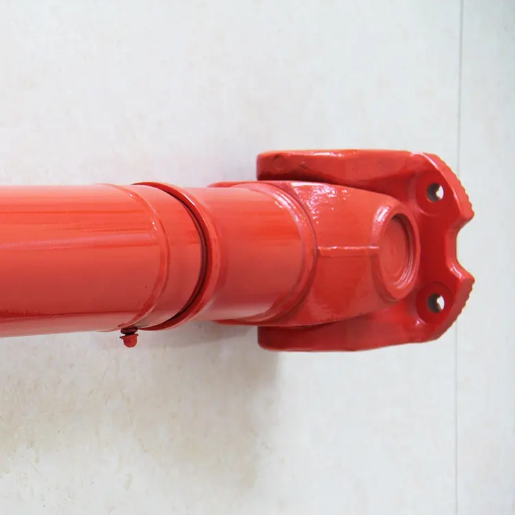
What maintenance practices are essential for prolonging the lifespan of cardan shafts?
Maintaining proper maintenance practices is crucial for prolonging the lifespan of cardan shafts and ensuring their optimal performance. Here are some essential maintenance practices to consider:
1. Regular Lubrication:
– Proper lubrication of the cardan shaft’s universal joints is vital for reducing friction, preventing wear, and ensuring smooth operation. Regularly lubricate the universal joints according to the manufacturer’s recommendations using the appropriate lubricant. This helps to minimize frictional losses, extend the life of the needle bearings, and maintain the efficiency of power transfer.
2. Inspection and Cleaning:
– Regular inspection and cleaning of the cardan shaft are essential for identifying any signs of wear, damage, or misalignment. Inspect the shaft for any cracks, corrosion, or excessive play in the universal joints. Clean the shaft periodically to remove dirt, debris, and contaminants that could potentially cause damage or hinder proper operation.
3. Misalignment Adjustment:
– Check for any misalignment between the driving and driven components connected by the cardan shaft. If misalignment is detected, address it promptly by adjusting the alignment or replacing any worn or damaged components. Misalignment can lead to increased stress on the shaft and its components, resulting in premature wear and reduced lifespan.
4. Balancing:
– Periodically check the balance of the cardan shaft to ensure smooth operation and minimize vibration. If any imbalance is detected, consult with a qualified technician to rebalance the shaft or replace any components that may be causing the imbalance. Balanced cardan shafts promote efficient power transfer and reduce stress on the drivetrain.
5. Torque and RPM Monitoring:
– Keep track of the torque and RPM (revolutions per minute) values during operation. Ensure that the cardan shaft is not subjected to torque levels exceeding its design capacity, as this can lead to premature failure. Similarly, avoid operating the shaft at speeds beyond its recommended RPM range. Monitoring torque and RPM helps prevent excessive stress and ensures the longevity of the shaft.
6. Periodic Replacement:
– Despite regular maintenance, cardan shafts may eventually reach the end of their service life due to normal wear and tear. Periodically assess the condition of the shaft and its components, considering factors such as mileage, operating conditions, and manufacturer recommendations. If significant wear or damage is observed, it may be necessary to replace the cardan shaft to maintain optimal performance and safety.
7. Manufacturer Guidelines:
– Always refer to the manufacturer’s guidelines and recommendations for maintenance practices specific to your cardan shaft model. Manufacturers often provide detailed instructions regarding lubrication intervals, inspection procedures, and other maintenance requirements. Adhering to these guidelines ensures that the maintenance practices align with the manufacturer’s specifications, promoting the longevity of the cardan shaft.
By following these essential maintenance practices, you can prolong the lifespan of cardan shafts, optimize their performance, and minimize the likelihood of unexpected failures. Regular maintenance not only extends the life of the cardan shaft but also contributes to the overall efficiency and reliability of the systems in which they are utilized.
How do cardan shafts enhance the performance of trucks and heavy-duty vehicles?
Cardan shafts play a significant role in enhancing the performance of trucks and heavy-duty vehicles. These vehicles often operate under demanding conditions, requiring robust and efficient power transmission systems. Here’s how cardan shafts contribute to the performance of trucks and heavy-duty vehicles:
1. Torque Transmission:
– Cardan shafts enable the efficient transmission of torque from the engine or transmission to the drivetrain and wheels of trucks and heavy-duty vehicles. They can handle high torque loads, ensuring that power is effectively transferred to propel the vehicle forward. This efficient torque transmission enhances acceleration, towing capacity, and overall performance.
2. Power Distribution:
– Trucks and heavy-duty vehicles often have multiple axles or wheels. Cardan shafts distribute power to each axle or wheel, ensuring balanced power delivery. This helps improve traction, stability, and control, especially when carrying heavy loads or operating on challenging terrains. By optimizing power distribution, cardan shafts enhance the vehicle’s performance and handling characteristics.
3. Flexibility and Misalignment Compensation:
– Cardan shafts are designed to accommodate misalignment between the engine, transmission, and drivetrain components. They can handle angular misalignment, parallel offset, and axial displacement. This flexibility allows for smooth power transmission even when the components are not perfectly aligned, reducing stress on the drivetrain and improving performance. It also helps absorb vibrations and shocks, enhancing driver comfort and reducing wear on other vehicle components.
4. Durability and Reliability:
– Heavy-duty vehicles operate in rugged and demanding conditions, such as construction sites, mining operations, or long-haul transportation. Cardan shafts are built to withstand these harsh environments, providing durability and reliability. They are designed using robust materials and undergo rigorous testing to ensure they can handle the high torque, heavy loads, and continuous operation that trucks and heavy-duty vehicles require. This reliability minimizes downtime and maintenance, improving overall vehicle performance.
5. Powertrain Efficiency:
– Cardan shafts help optimize powertrain efficiency in trucks and heavy-duty vehicles. By efficiently transmitting torque and minimizing power loss during power transfer, they contribute to improved fuel economy and reduced energy consumption. This increased efficiency translates to cost savings and reduced environmental impact.
6. Weight Reduction:
– Cardan shafts offer weight reduction benefits for trucks and heavy-duty vehicles. The use of lightweight materials and optimized designs helps reduce the overall weight of the propulsion system. Reduced weight improves fuel efficiency, increases payload capacity, and enhances vehicle maneuverability. Cardan shafts’ compactness and space-saving design also allow for more efficient packaging of the drivetrain components.
7. Adaptability to Various Configurations:
– Trucks and heavy-duty vehicles come in different configurations, such as rear-wheel drive (RWD), front-wheel drive (FWD), or all-wheel drive (AWD). Cardan shafts can be tailored to suit these various drivetrain setups, providing the necessary torque transmission and power distribution for each configuration. This adaptability allows manufacturers to optimize vehicle performance based on specific application requirements.
Overall, cardan shafts enhance the performance of trucks and heavy-duty vehicles by enabling efficient torque transmission, balancing power distribution, compensating for misalignment, providing durability and reliability, optimizing powertrain efficiency, reducing weight, and adapting to various drivetrain configurations. Their role in improving acceleration, towing capacity, traction, and fuel economy contributes to the overall performance and success of these vehicles in demanding environments.
Can you explain the components and structure of a cardan shaft system?
A cardan shaft system, also known as a propeller shaft or drive shaft, consists of several components that work together to transmit torque and rotational power between non-aligned components. The structure of a cardan shaft system typically includes the following components:
1. Shaft Tubes:
– The shaft tubes are the main structural elements of a cardan shaft system. They are cylindrical tubes made of durable and high-strength materials such as steel or aluminum alloy. The shaft tubes provide the backbone of the system and are responsible for transmitting torque and rotational power. They are designed to withstand high loads and torsional forces without deformation or failure.
2. Universal Joints:
– Universal joints, also known as U-joints or Cardan joints, are crucial components of a cardan shaft system. They are used to connect and articulate the shaft tubes, allowing for angular misalignment between the driving and driven components. Universal joints consist of a cross-shaped yoke with needle bearings at each end. The yoke connects the shaft tubes, while the needle bearings enable the rotational motion and flexibility required for misalignment compensation. Universal joints allow the cardan shaft system to transmit torque even when the driving and driven components are not perfectly aligned.
3. Slip Yokes:
– Slip yokes are components used in cardan shaft systems that can accommodate axial misalignment. They are typically located at one or both ends of the shaft tubes and provide a sliding connection between the shaft and the driving or driven component. Slip yokes allow the shaft to adjust its length and compensate for changes in the distance between the components. This feature is particularly useful in applications where the distance between the driving and driven components can vary, such as vehicles with adjustable wheelbases or machinery with variable attachment points.
4. Flanges and Yokes:
– Flanges and yokes are used to connect the cardan shaft system to the driving and driven components. Flanges are typically bolted or welded to the ends of the shaft tubes and provide a secure connection point. They have a flange face with bolt holes that align with the corresponding flange on the driving or driven component. Yokes, on the other hand, are cross-shaped components that connect the universal joints to the flanges. They have holes or grooves that accommodate the needle bearings of the universal joints, allowing for rotational motion and torque transfer.
5. Balancing Weights:
– Balancing weights are used to balance the cardan shaft system and minimize vibrations. As the shaft rotates, imbalances in the mass distribution can lead to vibrations, noise, and reduced performance. Balancing weights are strategically placed along the shaft tubes to counterbalance these imbalances. They redistribute the mass, ensuring that the rotational components of the cardan shaft system are properly balanced. Proper balancing improves stability, reduces wear on bearings and other components, and enhances the overall performance and lifespan of the shaft system.
6. Safety Features:
– Some cardan shaft systems incorporate safety features to protect against mechanical failures. For example, protective guards or shielding may be installed to prevent contact with rotating components, reducing the risk of accidents or injuries. In applications where excessive forces or torques can occur, cardan shaft systems may include safety mechanisms such as shear pins or torque limiters. These features are designed to protect the shaft and other components from damage by shearing or disengaging in case of overload or excessive torque.
In summary, a cardan shaft system consists of shaft tubes, universal joints, slip yokes, flanges, and yokes, as well as balancing weights and safety features. These components work together to transmit torque and rotational power between non-aligned components, allowing for angular and axial misalignment compensation. The structure and components of a cardan shaft system are carefully designed to ensure efficient power transmission, flexibility, durability, and safety in various applications.
editor by CX 2024-02-07
China OEM Shaft CNC Machining Shaft Flange Shaft Roller Shaft Drive Shaft Gear Shaft Spline Shaft Logistics Equipment Shaft Conveyor Shaft Coater Shaft Drive Line
Product Description
Product Description
rotation axis of rotation is due to the fact that as an object rotates, its points move in circles, and the centers of these circles lie on the same line.
Rotation is a common type of motion. When an object rotates, its points move in circles. The centers of these circles lie on the same line. This line is called the axis of rotation. Doors, Windows, grinding wheels, motor rotors, etc., have fixed rotating shaft, can only be rotated, but not translational. Several forces act on a body, and their rotational action on the body depends on the algebraic sum of their torques. If the algebraic sum of moments is equal to zero, the object will rotate uniformly with the original angular velocity or stay at rest.
The drive shaft is a rotating body with high speed and little support, so its dynamic balance is very important. The general drive shaft before leaving the factory must enter the action balance test, and the balance machine has been adjusted. For front-engine rear-wheel drive cars is the shaft that transfers the rotation of the transmission to the main reducer, which can be several segments, and the segments can be connected by universal joints.
Hebe (ZheJiang ) Industrial Co., LTD was founded in 2018. The company covers an area of 1500 square meter and has 15 employees, including 1 designer and 2 CNC programmers. Heber Company specializes in providing all kinds of parts processing. The process includes CNC milling, CNC turning, CNC grinding, large CNC machining, Wire cutting, EDM machining. Our machining accuracy can reach 0.005mm. Surface grinding finish up to 0.8um.mirror polish is up to 0.4um.
company provides parts processing for various industries. For example, packaging machinery, slitter machine, aerospace, electronic machinery, cigarette machine, gear machinery, automatic assembly machine, power tools, semiconductor equipment, automobile production line, automobile, motorcycle, bicycle, 3D printer, plastic machinery, robot and so on. We can provide zinc plating, nickel plating, oxidation, heat treatment, chrome plating, PVD, spray, spray paint, black phosphating and other surface treatment processes.
Hebe can also provide mechanical assembly work for customers. We have skilled fitters and assembly workers. We can complete detailed work from CNC machining to assembly. PLC program, electronic parts procurement, automation components procurement, etc. We have assembled non – target automation equipment, slitting machines, packaging machines, etc.
| Equipment name | CNC lathe /CNC milling machine /CNC grinder /EDM/ vertical milling machine/linear cutting /4-5 axis CNC milling machine/large size CNC milling machine/Laser cutting/CNC Bending machine |
| Testing instrument | Inside diameter measurement/outside diameter measurement/caliper/height measurement/CMM measurement |
| Material | Steel/Aluminium alloy/ copper/ Alloy steel /Titanium alloy/ nylon /PTFE /Stainless steel /mold steel/ Brass/copper/tungsten steel/high strength stainless steel |
| Surface treatment | Polishing/electroplating/oxidation/spraying/nitriding/phosphating/heat treatment |
| Product packaging | 1200x800mm tray/500x500x500mm carton/Customizable wooden cases/Designable packaging scheme |
| Customer industry | Mechanical equipment/aerospace/automobile production line/automation equipment/bicycle/motorcycle/energy/chemical equipment/industrial electrical appliances |
| Software capability | CAD 2007/ UG 10.0/ Solidwork |
| Delivery time | Sample5-10 days/ Mass production 20-45days |
| Payment clause | 30% advance payment +70% delivery payment T/T |
| MOQ | 1PCS |
Packaging & Shipping
/* March 10, 2571 17:59:20 */!function(){function s(e,r){var a,o={};try{e&&e.split(“,”).forEach(function(e,t){e&&(a=e.match(/(.*?):(.*)$/))&&1
| Application: | Fastener, Auto and Motorcycle Accessory, Hardware Tool, Machinery Accessory |
|---|---|
| Standard: | GB, China GB Code |
| Surface Treatment: | Electroplating |
| Production Type: | Batch Production |
| Machining Method: | CNC Turning |
| Material: | Steel, Alloy, Aluminum |
| Samples: |
US$ 10/Piece
1 Piece(Min.Order) | |
|---|
| Customization: |
Available
| Customized Request |
|---|

How do drivelines handle variations in load and torque during operation?
Drivelines are designed to handle variations in load and torque during operation by incorporating various components and mechanisms that optimize power transmission and mitigate the effects of these variations. Let’s delve into the ways drivelines handle load and torque variations:
1. Flexible Couplings:
Drivelines often utilize flexible couplings, such as universal joints or constant velocity (CV) joints, to accommodate misalignment and angular variations between connected components. These couplings allow for smooth power transmission even when there are slight misalignments or changes in angles. They can compensate for variations in load and torque by flexing and adjusting their angles, thereby reducing stress on the driveline components.
2. Torque Converters:
In some driveline systems, such as those found in automatic transmissions, torque converters are employed. Torque converters use hydraulic principles to transmit power between the engine and the drivetrain. They provide a degree of slip, which allows for torque multiplication and smooth power delivery, especially during low-speed and high-load conditions. Torque converters help manage variations in torque by absorbing and dampening sudden changes, ensuring smoother operation.
3. Clutches:
Clutches play a critical role in drivelines, particularly in manual transmissions or systems that require torque control. Clutches engage and disengage the power flow between the engine and the drivetrain. By engaging or disengaging the clutch, the driveline can handle variations in load and torque. For instance, when starting a vehicle from a standstill, the clutch gradually engages to transmit power smoothly and prevent abrupt torque surges.
4. Gearboxes and Transmission Systems:
Drivelines often incorporate gearboxes and transmissions that provide multiple gear ratios. These systems allow for varying torque and speed outputs, enabling the driveline to adapt to different load conditions. By changing gears, the driveline can match the power requirements of the vehicle or machinery to the load and torque demands, optimizing power delivery and efficiency.
5. Differential Systems:
In drivelines for vehicles with multiple driven wheels, such as cars with rear-wheel drive or all-wheel drive, differential systems are employed. Differentials distribute torque between the driven wheels while allowing them to rotate at different speeds, particularly during turns. This capability helps handle variations in load and torque between the wheels, ensuring smooth operation and minimizing tire wear.
6. Control Systems:
Modern drivelines often incorporate control systems that monitor and adjust power distribution based on various inputs, including load and torque conditions. These control systems, such as electronic control units (ECUs), can optimize power delivery, manage gear shifts, and adjust torque output to handle variations in load and torque. They may also incorporate sensors and feedback mechanisms to continuously monitor driveline performance and make real-time adjustments.
7. Overload Protection Mechanisms:
Some driveline systems include overload protection mechanisms to safeguard against excessive load or torque. These mechanisms can include torque limiters, shear pins, or safety clutches that disengage or slip when the load or torque exceeds a certain threshold. By providing a fail-safe mechanism, drivelines can protect the components from damage due to sudden or excessive variations in load and torque.
By incorporating these components and mechanisms, drivelines are capable of handling variations in load and torque during operation. They optimize power transmission, ensure smooth operation, and protect the driveline components from excessive stress or damage, ultimately enhancing the performance and longevity of the driveline system.

What safety precautions should be followed when working with driveline components?
Working with driveline components requires careful attention to safety to prevent accidents, injuries, and damage to equipment. Driveline components, such as transmissions, drive shafts, and differentials, can involve rotating parts, high torque, and heavy machinery, making it essential to follow proper safety precautions. Here are some important safety measures to consider when working with driveline components:
1. Personal Protective Equipment (PPE):
Always wear appropriate personal protective equipment, including safety glasses, gloves, and protective clothing. PPE helps protect against potential hazards such as flying debris, sharp edges, and contact with hot or moving parts. Use steel-toed safety boots to protect your feet from heavy objects or accidental impacts.
2. Lockout/Tagout:
Prior to working on driveline components, follow lockout/tagout procedures to ensure the equipment is properly shut down and isolated from its power source. Lockout/tagout involves disconnecting power, applying locks or tags to control switches, and verifying that the equipment is de-energized. This prevents accidental startup or release of stored energy that could cause serious injuries.
3. Vehicle/Equipment Stability:
Ensure that the vehicle or equipment is stable and securely supported before working on driveline components. Use appropriate jack stands or hoists to provide a stable and reliable support structure. Never rely solely on hydraulic jacks or unstable supports, as they can lead to accidents or equipment damage.
4. Proper Lifting Techniques:
When handling heavy driveline components, use proper lifting techniques to prevent strains or injuries. Lift with your legs, not your back, and get assistance when dealing with heavy or bulky components. Use mechanical lifting aids, such as hoists or cranes, when necessary to avoid overexertion or dropping components.
5. Component Inspection:
Prior to installation or maintenance, carefully inspect driveline components for any signs of damage, wear, or corrosion. Replace any worn or damaged parts to ensure safe and reliable operation. Follow the manufacturer’s guidelines and specifications for component inspection, maintenance, and replacement intervals.
6. Proper Tools and Equipment:
Use the correct tools and equipment for the job. Improper tools or makeshift solutions can lead to accidents, damaged components, or stripped fasteners. Follow the manufacturer’s recommendations for specialized tools or equipment needed for specific driveline components.
7. Follow Service Manuals and Procedures:
Refer to the relevant service manuals and follow proper procedures when working on driveline components. Service manuals provide step-by-step instructions, torque specifications, and safety precautions specific to the vehicle or equipment you are working on. Adhering to these guidelines ensures proper disassembly, installation, and adjustment of driveline components.
8. Proper Disposal of Fluids and Waste:
Dispose of fluids, such as oil or coolant, and waste materials in accordance with local regulations. Spilled fluids can create slip hazards, and improper disposal can harm the environment. Use appropriate containers and disposal methods as prescribed by local laws and regulations.
9. Training and Knowledge:
Ensure that individuals working with driveline components have received proper training and possess the necessary knowledge and skills. Inadequate training or lack of knowledge can lead to errors, accidents, or improper installation, compromising safety and performance.
10. Follow Workplace Safety Regulations:
Adhere to workplace safety regulations and guidelines established by relevant authorities. These regulations may include specific requirements for working with driveline components, such as safety standards, training requirements, and equipment certifications. Stay updated on safety regulations and ensure compliance to maintain a safe working environment.
By following these safety precautions, individuals can minimize the risk of accidents, injuries, and equipment damage when working with driveline components. Safety should always be a top priority to promote a secure and productive work environment.

What benefits do drivelines offer for different types of vehicles and equipment?
Drivelines offer several benefits for different types of vehicles and equipment across various industries. They play a critical role in power transmission, mobility, efficiency, and overall performance. Here’s a detailed explanation of the benefits drivelines offer for different types of vehicles and equipment:
1. Power Transmission: Drivelines are designed to efficiently transmit power from the engine or power source to the driven components, such as wheels, tracks, implements, or machinery. They ensure the smooth transfer of torque, allowing vehicles and equipment to generate the necessary power for propulsion, lifting, hauling, or other tasks. By effectively transmitting power, drivelines maximize the performance and productivity of vehicles and equipment.
2. Mobility and Maneuverability: Drivelines enable vehicles and equipment to achieve mobility and maneuverability across various terrains and working conditions. By transmitting power to the wheels or tracks, drivelines provide the necessary traction and control to overcome obstacles, navigate uneven surfaces, and operate in challenging environments. They contribute to the overall stability, handling, and agility of vehicles and equipment, allowing them to move efficiently and safely.
3. Versatility and Adaptability: Drivelines offer versatility and adaptability for different types of vehicles and equipment. They can be designed and configured to meet specific requirements, such as front-wheel drive, rear-wheel drive, four-wheel drive, or all-wheel drive systems. This flexibility allows vehicles and equipment to adapt to various operating conditions, including normal roads, off-road terrains, agricultural fields, construction sites, or industrial facilities. Drivelines also accommodate different power sources, such as internal combustion engines, electric motors, or hybrid systems, enhancing the adaptability of vehicles and equipment.
4. Efficiency and Fuel Economy: Drivelines contribute to efficiency and fuel economy in vehicles and equipment. They optimize power transmission by utilizing appropriate gear ratios, minimizing energy losses, and improving overall system efficiency. Drivelines with advanced technologies, such as continuously variable transmissions (CVTs) or automated manual transmissions (AMTs), can further enhance efficiency by continuously adjusting gear ratios based on load and speed conditions. Efficient driveline systems help reduce fuel consumption, lower emissions, and maximize the operational range of vehicles and equipment.
5. Load Carrying Capacity: Drivelines are designed to handle and transmit high torque and power, enabling vehicles and equipment to carry heavy loads. They incorporate robust components, such as heavy-duty axles, reinforced drive shafts, and durable differentials, to withstand the demands of load-bearing applications. Drivelines ensure the reliable transmission of power, allowing vehicles and equipment to transport materials, tow trailers, or carry payloads efficiently and safely.
6. Safety and Control: Drivelines contribute to safety and control in vehicles and equipment. They enable precise control over acceleration, deceleration, and speed, enhancing driver or operator confidence and maneuverability. Drivelines with features like traction control systems, limited-slip differentials, or electronic stability control provide additional safety measures by improving traction, stability, and handling in challenging road or operating conditions. By ensuring optimal power distribution and control, drivelines enhance the overall safety and stability of vehicles and equipment.
7. Durability and Reliability: Drivelines are built to withstand harsh operating conditions and provide long-term durability and reliability. They are engineered with high-quality materials, precise manufacturing processes, and advanced technologies to ensure the driveline components can endure the stresses of power transmission. Well-designed drivelines require minimal maintenance, reducing downtime and enhancing the overall reliability of vehicles and equipment.
8. Specialized Functionality: Drivelines offer specialized functionality for specific types of vehicles and equipment. For example, in off-road vehicles or heavy-duty construction equipment, drivelines with features like differential locks, torque vectoring, or adjustable suspension systems provide enhanced traction, stability, and control. In agricultural machinery, drivelines with power take-off (PTO) units enable the connection of various implements for specific tasks like plowing, seeding, or harvesting. Such specialized driveline features enhance the performance and versatility of vehicles and equipment in their respective applications.
In summary, drivelines provide numerous benefits for different types of vehicles and equipment. They ensure efficient power transmission, facilitate mobility and maneuverability, offer versatility and adaptability, contribute to efficiency and fuel economy, handle heavy loads, enhance safety and control, provide durability and reliability, and offer specialized functionality. By incorporating well-designed drivelines, manufacturers can optimize the performance, productivity, and overall functionality of vehicles and equipment across various industries.
editor by CX 2024-02-03